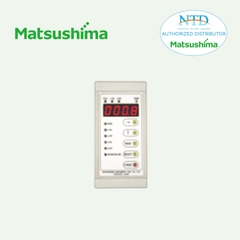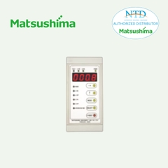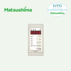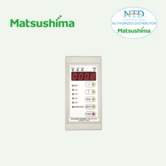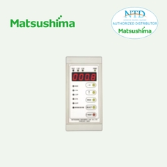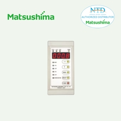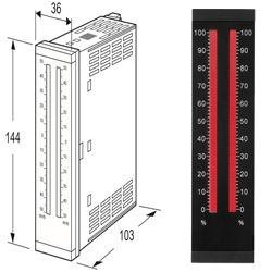
48NDR BARGRAPH INDICATING ALARM
Bargraph Indicators 48N Series
BARGRAPH INDICATING ALARM
(with 4-digit digital meter; RTD input)
Functions & Features
• Displays a process variable in graphic bargraph
of 101 LED segments
• Clear 4-digit digital meter
• Provides max. 4 alarm contact outputs
• Multi-color indicator
• Linearization and burnout
• LED brightness adjustment
• IP65 front cover
• Scale plate is easily replaced
• Separable terminal block
MODEL: 48NDR–[1][2][3]–[4][5]
ORDERING INFORMATION
• Code number: 48NDR-[1][2][3]-[4][5]
Specify a code from below for each of [1] through [5].
(e.g. 48NDR-424-R/CE/D/BL/Q)
• Temperature range (e.g. 0 – 200 °C)
• Bargraph scale (e.g. 0 – 100 %) (See ‘Scale Plate.’)
• Digital indicator scale (e.g. 0.0 – 200.0)
• Specify the specification for option code /Q
(e.g. /C01/SET)
[1] ALARM OUTPUT
0: None
2: 2 points
4: 4 points
[2] BAR LED COLOR
R: Red
Y: Amber
G: Green
B: Blue
1: Multi-color (red, orange and green), Pattern 1
(See ‘External View.’)
2: Multi-color (red, orange and green), Pattern 2
(See ‘External View.’)
[3] INPUT RTD (2- or 3-wire)
1: JPt 100 (JIS'89)
(Usable range: -200 to +500°C, -328 to +932°F; min.span: 50°C, 90°F)
3: Pt 100 (JIS'89)
(Usable range: -200 to +650°C, -328 to +1202°F; min.span: 50°C, 90°F)
4: Pt 100 (JIS'97, IEC)
(Usable range: -200 to +850°C, -328 to +1562°F; min.span: 50°C, 90°F)
5: Pt 50 Ω (JIS'81)
(Usable range: -200 to +500°C, -328 to +932°F; min.span: 100°C, 180°F)
6: Ni 508.4 Ω
(Usable range: -50 to +200°C, -58 to +392°F; min.span: 30°C, 54°F)
Note: Consult us for 2-wire RTD
[4] POWER INPUT
AC Power
M: 85 – 264 V AC (Operational voltage range 85 – 264 V, 50/60 Hz)
(CE or UKCA marking not available)
M2: 100 – 240 V AC (Operational voltage range 85 – 264 V, 50/60 Hz)
DC Power
R: 24 V DC
(Operational voltage range 24 V ±15 %, ripple 10 %p-p max.)
[5] OPTIONS (multiple selections)
Standards & Approvals
blank: Without CE
/CE: CE marking
/UK: CE, UKCA marking
Bezels
blank: Bezels for the 48 Series panel cutout
/D: Bezels for DIN panel cutout
/F: Bezels for Fuji Electric's PAJ, PAK, PBA panel cutout
Burnout
blank: Upscale burnout
/BL: Downscale burnout
Other Options
blank: none
/Q: Option other than the above (specify the specification)
SPECIFICATIONS OF OPTION: Q (multiple selections)
COATING (For the detail, refer to our web site.)
Moving parts and indicators are not coated.
/C01: Silicone coating
/C02: Polyurethane coating
/C03: Rubber coating
EX-FACTORY SETTING
/SET: Preset according to the Ordering Information Sheet
(No. ESU-9436)
BEZEL OPTION
Bezels are used to adapt the 48N Series to an existing panel cutout. In order to replace the 48 Series products, use the one attached to the 48N Series as standard. When the existing panel is cut according to DIN standard, specify ‘/D’ suffix code.
For a new installation, no bezel is required. Please refer to ‘Mounting Requirement’ and mount the 48N directly.
Ingress protection is invalid when the 48N is mounted with a bezel, or when multiple modules are stacked side by side.
SPARE PARTS
• Scale plate
GENERAL SPECIFICATIONS
Construction: Panel flush mounting
Degree of protection: IP65; applicable to the front panel for single unit mounted according to the specified panel cutout
Connection: M3 separable screw terminal (torque 0.6 N·m)
Screw terminal: Nickel-plated steel
Housing material: Flame-resistant resin (black)
Isolation: Input to output to power
Zero adjustment: 0 – 10 % (front)
Span adjustment: 90 to 100 % (front)
Scale plate: Flame resistant resin (white scale & characters on black base)
H & L alarm output delay: 0 sec. (factory setting; fieldselectable between 0 and 15 sec. by 1 sec. increments)
Setpoint adjustment
2 points:
H [L setpoint ] to 100 %
L 0 to [H setpoint]
or No alarm trip
4 points:
HH [H setpoint] to 100 %
H [L setpoint] to [HH setpoint]
L [LL setpoint] to [H setpoint]
LL 0 to [L setpoint]
or No alarm trip
Alarm deadband (hysteresis): 1 %
Burnout: Upscale standard; downscale optional.
The 100 % position bargraph segment and 115 % value of the digital meter blink with upscale burnout; the 0 % position bargraph segment and -15 % value of the digital meter blink with downscale burnout.
Linearization: Standard
Setting: (Front button)
• Zero and span adjustments
• Alarm setpoint
• Others
(Refer to the instruction manual for details)
Read rate: 10/s
Moving average sample number: 4 (factory setting; field selectable among 1, 2, 4, 8 or 16)
LED brightness adjustment: 7 levels
■ BARGRAPH
LED: 101-segment LED, 100 mm (3.96”) long, 3.00 mm (.12”) wide
Display range: 0 to 100 (scaling function not available)
(0 % or 100 % position bar blinks when over range)
Scale: Two different scales available for single bargraph
Characters: Max. 4 characters including decimal point and negative sign
Divisions: Min. 22, max. 100
Engineering unit: Max. 6 characters
■ DIGITAL DISPLAYS
LED: 7-segment red LED, character 8 mm (.31”) high
Number of digits: 4 digits
Setting range: -1999 to 9999
(Min. 3 significant digits)
Minimum scale value: 100 (3 digits, the decimal point position disregarded)
Scaled range: The range between -1999 to 9999 and -15 to
+115 % of input span
(The indicator blinks when the input is out of the range)
Decimal point position: 10–1, 10–2, 10–3 or none
Zero indication: Higher-digit zeros are suppressed
Engineering unit: Max. 6 characters on scale plate
INPUT SPECIFICATIONS
Maximum leadwire resistance: 200 Ω per wire (3-wire)
Sensing current: ≤ 1 mA
OUTPUT SPECIFICATIONS
■ Alarm Output: Relay contact
Rated load: 250 V AC @1 A (cos ø = 1)
30 V DC @5 A (resistive load)
Maximum switching voltage: 250 V AC, 220 V DC
Maximum switching power: 380 VA, 150 W
Minimum load: 5 V DC @100 mA
Mechanical life: ≥ 5 × 10⁸ cycles (rate 180 cycles/min.)
INSTALLATION
Power Consumption
•AC:
Approx. 5.5 VA at 100 V with max. load
Approx. 7 VA at 200 V with max. load
Approx. 8 VA at 264 V with max. load
•DC
Approx. 3.5 W at 20.4 V with max. load
Approx. 3.5 W at 24 V with max. load
Approx. 3.5 W at 27.6 V with max. load
Operating temperature: -5 to +55°C (23 to 131°F)
Operating humidity: 30 to 90 %RH (non-condensing)
Mounting: Panel flush mounting
Weight: 300 g (0.66 lb)
PERFORMANCE in percentage of span
Accuracy
Bargraph: ±1 % ±1 digit
Digital indicator, alarm output: ±0.5 % ±1 digit
Temp. coefficient: ±0.015 % of FS/°C (±0.008 % of FS/°F)
Response time: ≤ 0.5 sec.
(moving average sample number set to 4)
Burnout response: ≤ 10 sec.
Insulation resistance: ≥ 100 MΩ with 500 V DC
Dielectric strength: 2000 V AC @1 minute (input to output to power to ground)
STANDARDS & APPROVALS
EU conformity:
EMC Directive
EMI EN 61000-6-4
EMS EN 61000-6-2
Low Voltage Directive
EN 61010-1
Measurement Category II (output)
Installation Category II (power)
Pollution Degree 2
Input to output to power: Reinforced insulation (300 V)
RoHS Directive
UK conformity (UKCA):
The UK legislations and designated standards are equivalent to the applicable EU directives.
(Refer to our website for more information about the legislations and designated standards.)


