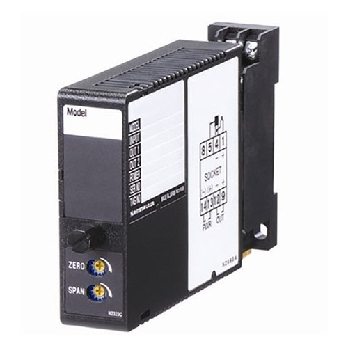
M2PRU PULSE SCALER
M2PRU PULSE SCALER
(field-configurable)
Functions & Features
• Converts pulse rate into convenient engineering unit for display on a totalizing counter or meter
• Excitation
• Scaling factor adjustable of 1.0000 × 100 to 0.0001 × 10⁻⁶
• Various outputs (open collector, voltage pulse and AC/DC switch)
• Three-way isolation
Typical Applications
• Positive displacement flowmeters and turbine flowmeters
• Magnetic tachometers
MODEL: M2PRU–[1][2][3]–[4][5]
ORDERING INFORMATION
• Code number: M2PRU-[1][2][3]-[4][5]
Specify a code from below for each of [1] through [5].
(e.g. M2PRU-A24A-M2/CE/Q)
• Scaling factor (e.g. 0.7000 × 10⁻²)
• Specify the specification for option code /Q
(e.g. /C01/S01)
[1] INPUT
A1: Open collector
A2: Mechanical contact
C: Voltage pulse (sensitivity 2 V)
H: Two-wire current pulse
[2] EXCITATION
4: 12 V DC / 30 mA
7: 24 V DC / 30 mA
[3] OUTPUT
A: Open collector (max. 100 kHz)
M: 5 V pulse (max. 100 kHz)
N: 12 V pulse (max. 100 kHz)
P: 24 V pulse (max. 100 kHz)
R: AC/DC switch (max. 1 kHz)
(‘/UL’ is not selectable for ‘Standards & Approvals’ code.)
( ) = Max. frequency
[4] POWER INPUT
AC Power
M2: 100 – 240 V AC (Operational voltage range 85 – 264 V,
47 – 66 Hz)
(90 – 264 V for UL)
DC Power
R: 24 V DC
(Operational voltage range 24 V ±10 %, ripple 10 %p-p max.)
R2: 11 – 27 V DC
(Operational voltage range 11 – 27 V, ripple 10 %p-p max.)
(Select ‘/N’ for ‘Standards & Approvals’ code.)
P: 110 V DC
(Operational voltage range 85 – 150 V, ripple 10 %p-p max.)
(110 V ±10 % for UL)
[5] OPTIONS (multiple selections)
Standards & Approvals (must be specified)
/N: Without CE or UL
/CE: CE marking
/UL: UL approval, CE marking
Other Options
blank: none
/Q: Option other than the above (specify the specification)
SPECIFICATIONS OF OPTION: Q (multiple selections)
COATING (For the detail, refer to our web site.)
/C01: Silicone coating
/C02: Polyurethane coating
/C03: Rubber coating (UL not available)
/C04: Polyolefin coating (UL not available)
TERMINAL SCREW MATERIAL
/S01: Stainless steel (UL not available)
CAUTION
1) The M2PRU’s output waveform is not uniform due to its scaling method. The user must be aware that it may be inconvenient for certain types of application.
2) The M2PRU is designed to accept at the maximum of 100 kHz, which may cause errors due to chattering in the input pulses.
A filter circuitry (time constant: approx. 1 msec.) is incorporated to eliminate unwanted chattering when the mechanical contact input is specified. It is effective for most relay types, however, an external CR filter as indicated below, could be added if the user need improvement. Limit the input frequency to 10 Hz at maximum.
GENERAL SPECIFICATIONS
Construction: Plug-in
Connection: M3 screw terminals (torque 0.8 N·m)
Screw terminal: Chromated steel (standard) or stainless steel
Housing material: Flame-resistant resin (black)
Isolation: Input to output to power
Chattering protection: Filter provided for mechanical contact input (time constant: approx. 1 msec.)
Input pulse sensing: DC coupled; capacitor coupling (automatic trigger*) is field selectable with the side DIP switch for the voltage pulse input.
*Capacitor coupling, with which the detecting levels are automatically set within two peaks of the waveforms, is effective way to detect those with DC offset. However, it may be ineffective if the duty ratio is extremely high or low. The automatic trigger method can compensate such irregular pulses.
Scaling factor adjustment: 10-position rotary switch; 1.0000 × 100 – 0.0001 × 10⁻⁶; factory set to 1.0000 × 100 if not specified when ordering
Output pulse width adjustment: Single-turn screwdriver adjustment (front); 5 μsec. – 400 msec. (one-shot type); Factory set to 5 μsec. except for the mechanical contact input set to 15 msec. or AC/DC switch output set to 500 μsec.
(Min. 400 μsec. recommended for AC/DC switch output of which the internal voltage drop value may increase with a shorter pulse width.)
Output pulse width range selector: Double-throw SW (front)
INPUT SPECIFICATIONS
Excitation: Shortcircuit protection; limited to approx. 40 mA at shortcircuit
■ Open Collector
Frequency range: 0 – 100 kHz
Pulse width time requirement: Min. 5 μsec. for ON and OFF
Sensing: Approx. 24 V DC @2 mA
Detecting levels: ≤ 400 Ω / 0.8 V for ON,
≥ 1200 Ω / 2.4 V for OFF
■ Mechanical Contact
Frequency range: 0 – 30 Hz
Pulse width time requirement: Min. 10 msec. for ON and OFF
Sensing: Approx. 24 V DC @2 mA
Detecting levels: ≤ 400 Ω / 0.8 V for ON,
≥ 1200 Ω / 2.4 V for OFF
■ Voltage Pulse
Waveform: Square or sine
Frequency range: 0 – 100 kHz
(min. 10 Hz for sine waves)
Pulse width time requirement: ≥ 5 μsec. for high and low levels
Input impedance: ≥ 10 kΩ
Max. input voltage across the terminals: ±50 V
Detecting levels
DC coupled: ≥ 2 V DC for high level; ≤ 1 V DC for low level
Capacitor coupled: ≥ 2 Vp-p
■ Two-wire Current Pulse
Frequency range: 0 – 100 kHz
Pulse width time requirement: Min. 5 μsec. for high and low levels
Detecting levels:
≥ 10 mA for high level
≤ 5 mA for low level
Maximum current: ±30 mA
Input resistance: Receiving resistor 200 Ω
OUTPUT SPECIFICATIONS
■ Open Collector: 50 V DC @200 mA (resistive load)
Maximum frequency: 100 kHz
Saturation voltage: 0.6 V DC
■ Voltage Pulse
Maximum frequency: 100 kHz
High level: Rating (5, 12 or 24 V) ±10 %
Low level: ≤ 0.5 V
Load resistance:
≥ 500 Ω for 5 V
≥ 1200 Ω for 12 V
≥ 4800 Ω for 24 V
■ AC/DC Switch
132 V AC @200 mA (cos ø = 1)
30 V DC @200 mA (resistive load)
Maximum frequency: 1 kHz
Internal voltage drop: ≤ 3 V
INSTALLATION
Power Consumption
•AC:
Approx. 4 VA at 100 V
Approx. 5 VA at 200 V
Approx. 6 VA at 264 V
•DC: Approx. 3 W
Operating temperature: -5 to +55°C (23 to 131°F)
Operating humidity: 30 to 90 %RH (non-condensing)
Mounting: Surface or DIN rail
Weight: 150 g (0.33 lb)
PERFORMANCE
Response time: 25 μsec. + input cycle + output cycle
(time required for the first pulse to be output from a train of pulse input)
Insulation resistance: ≥ 100 MΩ with 500 V DC
Dielectric strength: 2000 V AC @1 minute (input to output to power to ground)
STANDARDS & APPROVALS
EU conformity:
EMC Directive
EMI EN 61000-6-4
EMS EN 61000-6-2
Low Voltage Directive
EN 61010-1
Measurement Category II (output)
Installation Category II (power)
Pollution Degree 2
Open collector/voltage pulse output
Input or output to power: Reinforced insulation (300 V)
Input to output: Basic insulation (300 V)
AC/DC switch output
Input or output to power: Reinforced insulation (300 V)
Input to output: Reinforced insulation (300 V)
RoHS Directive
Approval:
UL/C-UL nonincendive Class I, Division 2,
Groups A, B, C, and D
(ANSI/ISA-12.12.01, CAN/CSA-C22.2 No.213)
UL/C-UL general safety requirements
(UL 61010-1, CAN/CSA-C22.2 No.61010-1)
EXTERNAL VIEW
Refer to the instruction manual for detailed procedures.


