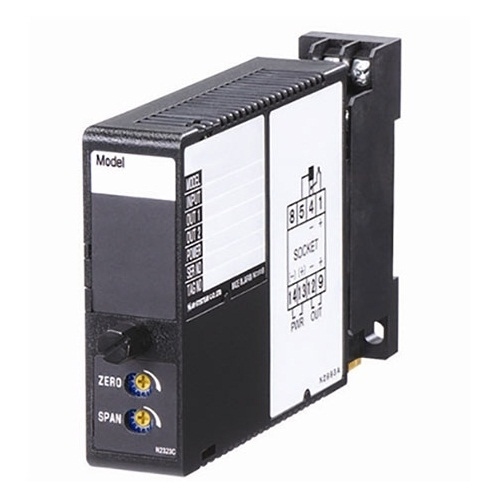
YPD PULSE ISOLATOR
YPD PULSE ISOLATOR
(built-in excitation)
Functions & Features
• Galvanically isolating pulse rate signals
• Input frequency = output frequency
• Various outputs (relay, open collector and voltage pulses)
• Excitation
• Isolation up to 2000 V AC
• High-density mounting
Typical Applications
• Isolating field pulse signals in order to reduce noises
• Changing e.g. dry contact signal to e.g. 5 V signals
MODEL: YPD–[1][2][3][4][5]–[6][7]
ORDERING INFORMATION
• Code number: YPD-[1][2][3][4][5]-[6][7]
Specify a code from below for each of [1] through [7].
(e.g. YPD-D4A23N-B/Q)
• Use Ordering Information Sheet (No. ESU-1369) for pulse width settings of DC voltage pulse input or one-shot output.
• Specify the specification for option code /Q
(e.g. /C01/S01)
[1] INPUT
A: Dry contact
B: DC Voltage pulse (Specify sensitivity)
C: 5 V pulse (sensitivity 2 V)
D: 12 V/24 V pulse (sensitivity 5 V)
H: Two-wire current pulse
[2] EXCITATION
1: 5 V DC / 80 mA
4: 12 V DC / 40 mA
[3] OUTPUT
A1: Open collector (max. frequency 100 kHz)
A2: Open collector (max. frequency 10 Hz)
M1: 5 V pulse (max. frequency 100 kHz)
M2: 5 V pulse (max. frequency 10 Hz)
N1: 12 V pulse (max. frequency 100 kHz)
N2: 12 V pulse (max. frequency 10 Hz)
H: Relay contact (max. frequency 0.5 Hz)
[4] OUTPUT PULSE WIDTH
1: Equal to the input
2: One-shot output (≤ 30 msec.; std. pulse width 5 msec.)
(Specify when optional pulse width is required.)
(10 msec. for relay contact pulse)
3: One-shot output (≥ 30 msec.; std. pulse width 50 msec.)
(Specify when optional pulse width is required.)
[5] OUTPUT LOGIC
N: The same as the input
R: Inverted
[6] POWER INPUT
AC Power
B: 100 V AC
C: 110 V AC
D: 115 V AC
F: 120 V AC
G: 200 V AC
H: 220 V AC
J: 240 V AC
DC Power
S: 12 V DC
R: 24 V DC
V: 48 V DC
[7] OPTIONS
blank: none
/Q: With options (specify the specification)
SPECIFICATIONS OF OPTION: Q (multiple selections)
COATING (For the detail, refer to our web site.)
/C01: Silicone coating
/C02: Polyurethane coating
/C03: Rubber coating
TERMINAL SCREW MATERIAL
/S01: Stainless steel
GENERAL SPECIFICATIONS
Construction: Plug-in
Connection: M3.5 screw terminals
Screw terminal: Chromated steel (standard) or stainless steel
Housing material: Flame-resistant resin (black)
Isolation: Input to output to power
Excitation adjustment: 5 – 12 V DC
Detecting level adjustments (DC voltage pulse): 2 – 10 V
Input pulse sensing: DC coupled
Input filter: Provided with output code A2, M2, N2, H
(time constant approx. 1 msec.)
INPUT SPECIFICATIONS
Excitation: Shortcircuit protection; approx. 150 mA at
shortcircuit
■ Dry Contact
Max. frequency: 100 kHz
Pulse width time requirement: 5 μsec. min. (10 ms
for output code A2, M2, N2, H)
Sensing: 10 V DC @ 2.5 mA
ON/OFF level:
≥ 5.5 kΩ /5.5 V for OFF
≤ 1.8 kΩ /4.5 V for ON
■ Voltage Pulse: Specify DC offset and amplitude.
Max. frequency: 100 kHz
Pulse width time requirement: 5 μsec. min. (10 ms
for output code A2, M2, N2, H)
Waveform: Square or sine
Input impedance: 10 kΩ min.
Input amplitude: 2 – 50 Vp-p
Sensitivity adjustment (threshold level): 2 – 10 V
Max. voltage between input terminals: 50 V
• 5V, 12V, 24V Pulse
Waveform: Square or sine
Input impedance: 10 kΩ min.
Detecting level
INPUT 5 V PULSE 12 V / 24 V PULSE
VH ≥ 2.25 V ≥ 5.25 V
VL ≤ 1.75 V ≤ 4.75 V
■ Two-wire Current Pulse
Max. frequency: 100 kHz
Pulse width time requirement: 5 μsec. min. (10 ms
for output code A2, M2, N2, H)
Input resistance: Receiving resistor 220 Ω
Maximum current: ± 50 mA
Hi/Lo level: ≤ 5 mA for Lo, ≥ 15 mA for Hi
OUTPUT SPECIFICATIONS
■ Open Collector: 50 V DC @ 50 mA (resistive load)
Maximum frequency:
Output code A1: 100 kHz with load resistance ≤ 1 kΩ
OUtput code A2: 10 Hz with load resistance ≤ 1 kΩ
Saturation voltage: 0.5 V DC
■ Voltage Pulse: Rating (5 or 12 V) ± 10 %
Maximum frequency: 100 kHz
Load resistance: 1.5 kΩ min. for 5 V, 3 kΩ min. for 12 V
L level: ≤ 0.5 V
■ Relay Contact: 120 V AC or 30 V DC @ 200 mA
(resistive load)
Maximum switching voltage: 250 V AC or 30 V DC
Maximum switching power: 50 VA or 6 W
Minimum load: 5 V DC @ 10 mA
Maximum frequency: 0.5 Hz
Relay life:
2 × 10⁷ cycles (mechanical)
7 × 10⁶ cycles (electrical)
OUTPUT PULSE WIDTH
•Equal to the Input: No pulse width conversion
(difference between input and output within ±10 μsec.)
• One-shot Output: Constant pulse width
Output Frequency (Hz) = 500 / (Output Pulse Width (msec.))
Adjustable pulse width
Pulse width max. 30 msec. (code 2):
1 – 30 msec. adjustable (standard 5 msec. ±20 %) for 'Output' code other than 'H'
10 – 30 msec. adjustable (standard 10 msec. ±20 %) for 'Output' code 'H'
Pulse width min. 30 msec. (code 3): 30 msec. – 1 sec. adjustable (standard 50 msec. ±20 %)
INSTALLATION
Power input
• AC: Operational voltage range: rating ±10 %,
50/60 ± 2 Hz, approx. 2.5 VA
•DC: Operational voltage range: rating ±10 %,
ripple 10 %p-p max., approx. 2 W (80 mA at 24 V)
Operating temperature: -5 to +60°C (23 to 140°F)
Operating humidity: 30 to 90 %RH (non-condensing)
Mounting: Surface or DIN rail
Weight: 400 g (0.88 lb)
PERFORMANCE
Insulation resistance: ≥ 100 MΩ with 500 V DC
Dielectric strength: 2000 V AC @1 minute (input to output to power to ground)
EXTERNAL VIEW
OUTPUT LOGIC
EXTERNAL DIMENSIONS & TERMINAL ASSIGNMENTS unit: mm [inch]
SCHEMATIC CIRCUITRY & CONNECTION DIAGRAM
| YPD-A4N21N-H, |


