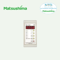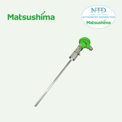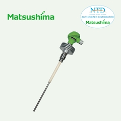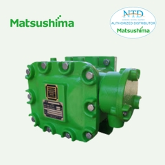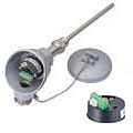
27HU 2-WIRE UNIVERSAL TEMPERATURE TRANSMITTER
2-WIRE UNIVERSAL TEMPERATURE TRANSMITTER
(HART communication)
Functions & Features
• Universal input: DC mV, T/C, RTD and resistance
• High accuracy
• HART communication
• Intrinsically safe approval
• Suitable for Functional Safety applications up to SIL2
• Programming via hand-held communicator or via PC
• A wide variety of T/C and RTD types
• User’s temperature table can be used
• Self diagnostics
• Ultra-low temp. drift option (20 ppm/°C typ.)
• CE marking (conforms to ATEX and EMC)
MODEL: 27HU–[1][2]
ORDERING INFORMATION
• Code number: 27HU-[1][2]
Specify a code from below for each of [1] and [2].
(e.g. 27HU-2/L)
Use Ordering Information Sheet (No. ESU-7651). Factory standard setting will be used if not otherwise specified.
Specify the country in which the product is to be used with the Safety Approval code 2.
[1] SAFETY APPROVAL
0: None
1: FM intrinsically safe
2: ATEX intrinsic safety
[2] OPTIONS
Temperature Drift
Blank: Standard (temp. coefficient 0.015%/°C)
/L: Ultra-low temperature drift
(temp. coefficient 0.002%/°C typ., 0.005%/°C max.)
RELATED PRODUCTS
• USB interface Bell202 modem (model: COP-HU)
Usable in ‘non-hazardous’ area only.
• Hand-held communicator
• PC configurator software (model: 27HUCFG)
Downloadable at our web site.
GENERAL SPECIFICATIONS
Construction: Sensor head-mounting
Connection: M3 screw terminals (torque 0.5 N·m)
Screw terminal: Nickel-plated brass
Housing material: Flame-resistant resin (black)
Isolation: Input to output
User-configurable items:
• Input sensor type and numbers
• Number of wires (RTD & resistance)
• Input range (inverted range selectable)
• Burnout
• Output limits (Upper / Lower)
• Damping time (factory set to 0)
• Cold junction compensation (T/C; internal or external
sensor selectable)
• Linearization
• Sensor calibration
• Output calibration
• HART communication mode
Refer to the HART setup manual or the PC configurator users manual for the detail.
HART COMMUNICATION
Protocol: HART communication protocol
HART address range: 0 – 15 (factory set to 0)
Transmission speed: 1200 bps
Digital current: Approx. 1 mAp-p when communicating
Character format: 1 Start Bit, 8 Data Bits, 1 Odd Parity Bit,
1 Stop Bit
Distance: 1.5 km (0.9 miles)
HART communication mode: Master-Slave Mode and Burst Mode (factory set to Master-Slave)
HART network mode: Point-to-Point Mode and Multi-drop Mode; automatically set to Multi-drop Mode when the address is set to other than 0.
INPUT SPECIFICATIONS
The input is factory set for use with K thermocouple, single input, 0 to 100°C, internal CJC sensor.
See Table 1 for the available input type, the minimum span and the maximum range.
■ DC mV (dual input available)
Input resistance: ≥ 1 MΩ
■ Thermocouple (dual input available)
Input resistance: ≥ 1 MΩ
Burnout sensing: 33 μA
External CJC sensor type: Pt 100
■ RTD (2-wire, 3-wire or 4-wire)
Input resistance: ≥ 1 MΩ
Excitation: 0.2 mA
Allowable leadwire resistance: Max. 10 Ω per wire
■ Resistance (2-wire, 3-wire or 4-wire)
Input resistance: ≥ 1 MΩ
Excitation: 0.2 mA
Allowable leadwire resistance: Max. 10 Ω per wire
OUTPUT SPECIFICATIONS
Output range: 4 – 20 mA DC
Operational range: 3.75 – 23 mA
Load resistance vs. supply voltage:
Load Resistance (Ω) = (Supply Voltage (V) – 8 (V))
÷ 0.023 (A) (including leadwire resistance)
Burnout: 3.75 – 3.8 mA or 21.5 – 23 mA
(factory set to 23 mA)
Upper output limit proportional to the input:
20 – 21.5 mA (factory set to 21.5 mA)
Lower output limit proportional to the input:
3.8 – 4 mA (factory set to 3.8 mA)
Update time: 440 msec. (660 msec. with dual input)
Output characteristics for dual input:
Average or Differential selectable
INSTALLATION
Supply voltage
• 8 – 35 V DC (non-approved)
• 8 – 28 V DC (approved)
Operating temperature: -40 to +85°C (-40 to +185°F)
(See Safety Parameters for use in a hazardous location.)
Operating humidity: 0 to 95 %RH (non-condensing)
Mounting: Head-mounting (DIN type B head)
Weight: 50 g (1.76 oz)
PERFORMANCE
Accuracy: See Table 1.
Cold junction compensation accuracy: ±0.5°C (±0.9°F) with internal CJC sensor
Response time: ≤ 2 sec. (0 – 90 %) with damping time
set to 0 and when not communicating via HART.
Supply voltage effect: ±0.005 % of span/V
Insulation resistance: ≥ 100 MΩ with 500 V DC
Dielectric strength: 1500 V AC @1 minute (input to output)
Safety integrity level according to IEC 61508: Suitable for use in a safety instrumented system up to SIL2 (together with sensor) if appropriate safety instructions are observed. Consult us.
STANDARDS & APPROVALS
EU conformity:
ATEX Directive
Ex ia EN 60079-11
EMC Directive
EN 61326-1
RoHS Directive
Safety approval:
FM: Intrinsically safe
Class I, Division 1, Groups A, B, C and D
Class I, Zone 0, AEx ia IIC (US)
Class I, Zone 0, Ex ia IIC (Canada)
T4, T5 and T6
(Class 3610, ANSI/ISA 60079-11,
CAN/CSA-C22.2 No. 157,
CAN/CSA-C22.2 No. 60079-11)
SAFETY PARAMETERS
Operating temperature
For ATEX / FM:
T4: -40 to +80°C
T5: -40 to +60°C
T6: -40 to +45°C
Ex-data:
• Output circuit
Ui (Vmax): 30 V DC
Ii (Imax): 96 mA DC
Pi (Pmax): 720 mW
Ci: 1 nF
Li: 0 mH
• Sensor circuit
Uo (Voc): 30 V DC
Io (Isc): 24 mA DC
Po: 180 mW
Co (Ca): 50 nF
Lo (La): 40 mH


