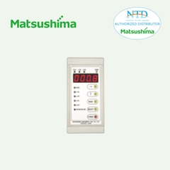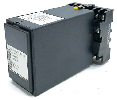
JB2 ANALOG BACKUP STATION
JB2
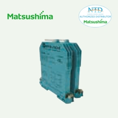
Plug-in Signal Conditioners M-UNIT
ANALOG BACKUP STATION
Functions & Features
• Enables manual loading providing hold/increase/ decrease signals to a device controlled by PID controller
• When the PID controller fails, the JB2 output goes back the preset time period and holds the cascade control signal of that moment (Retroactive function)
• Cascade control loop does not open even when the JB2 itself fails
• Manual control output transits smoothly to the cascade control mode in the preset response time (Sliding-back function)
• Isolated re-transmitted output
• Parameters set via hand-held programmer PU-2x
• Can be driven on battery power supply (35 V DC max.)
Typical Applications
• Backup hold/manual loading for the DCS or computer control output failure
MODEL: JB2–AAA–R1/A[1]
ORDERING INFORMATION
• Code number: JB2-AAA-R1/A[1]
Specify a code from below for [1].
(e.g. JB2-AAA-R1/A/Q)
• Use Ordering Information Sheet (No. ESU-2642) to specify details of the backup operation mode.
Factory setting (table below) will be used if not otherwise specified.
• Specify the specification for option code /Q
(e.g. /C01/S01)
CAS INPUT
Current
A: 4 – 20 mA DC
MV OUTPUT
Current
A: 4 – 20 mA DC
RE-TRANSMITTED OUTPUT
Current
A: 4 – 20 mA DC (Load resistance 350 Ω max.)
POWER INPUT
DC Power
R1: 15 – 35 V DC
(Operational voltage range 15 – 35 V, ripple 10 %p-p max.)
OUTPUT SELECTABLE AFTER POWER RECOVERY
/A: With
[1] OPTIONS
blank: none
/Q: With options (specify the specification)
SPECIFICATIONS OF OPTION: Q (multiple selections)
COATING (For the detail, refer to our web site.)
/C01: Silicone coating
/C02: Polyurethane coating
/C03: Rubber coating
TERMINAL SCREW MATERIAL
/S01: Stainless steel
RELATED PRODUCTS
• Programming Unit (model: PU-2x)
• PC configurator software (model: JXCON)
Downloadable at our web site.
A dedicated cable is required to connect the module to the PC. Please refer to the internet software download site or the users manual for the PC configurator for applicable cable types.
GENERAL SPECIFICATIONS
Construction: Plug-in
Connection: M3.5 screw terminals
Screw terminal: Chromated steel (standard) or stainless steel
Housing material: Flame-resistant resin (black)
Isolation: CAS input or MV output to contact input or power to re-transmitted output to contact output
Zero adjustment: -5 to +5 % (front)
Span adjustment: 98 to 102 % (front)
Indicator LED: RUN output (green), MAN status output (red), UP command (red), DOWN command (red), MAN command (red)
Programming: Programming Unit (model: PU-2x); Sliding-back response time, UP-DOWN response time, alarm, etc.
(Refer to the users manual of JXCON for the adjustments configurable with JXCON.)
Alarm output: RUN contact turns off when the high/low alarm for the CAS input trips.
INPUT SPECIFICATIONS
■ CAS Input: 4 – 20 mA DC
Input resistance: 25 Ω in manual control mode
■ Contact Input: MAN control command and UP/DOWN command
Sensing: 5 V DC @ 3 mA
Detection levels
ON resistance: ≤ 200 Ω, ≤ 0.80 V
OFF resistance: ≥ 100 kΩ, ≥ 4.95 V
OUTPUT SPECIFICATIONS
■ MAN Output: 4 – 20 mA DC
Load resistance
• CAS control mode: Allowable load for CAS signal minus
50 Ω
• MAN control mode: 0 – 750 Ω
■ Relay Output: MAN status and RUN output;
120 V AC @ 1 A or 24 V DC @ 1 A
Maximum switching voltage: 250 V AC or 30 V DC
Maximum switching power: 120 VA or 24 W
Minimum load: 5 V DC @100 mA
Mechanical life: 2 × 10⁷ cycles
INSTALLATION
Current consumption
CAS mode: Approx. 120 mA at 24 V
MAN mode: Approx. 180 mA at 24 V
Operating temperature: -5 to +55°C (23 to 131°F)
Operating humidity: 30 to 90 %RH (non-condensing)
Mounting: Surface or DIN rail
Weight: 450 g (0.99 lb)
PERFORMANCE in percentage of span
Alarm setting accuracy: ±0.5 %
Re-transmitted output accuracy: ±0.4 %
CAS to MAN or MAN to CAS switching accuracy: ±0.5 %
MV output terminal is open during the time switching the internal relay (≤ 10 msec.) when turning CAS to MAN or MAN to CAS mode.
Temp. coefficient: ±0.015 %/°C (±0.008 %/°F)
Re-transmitted output response time: ≤ 20 msec.
Output memory at power OFF: E2PROM (non-volatile memory)
Insulation resistance: ≥ 100 MΩ with 500 V DC
Dielectric strength: 1000 V AC @ 1 minute (CAS input or MV output to contact input or power to retransmitted output to contact output)
1500 V AC @ 1 minute (CAS input or MV output or contact input or power or re-transmitted output or contact output to ground)
OPERATING MODES
■ CASCADE CONTROL MODE
The JB2 allows the CAS input (cascade control signal) from the PID controller to pass through at the MV output terminals.
■ MANUAL CONTROL MODE
When the external MAN command contact is closed, the JB2 turns on to manual control mode. Actual output signal is determined by following three operation modes:
MODE 1: Holds the CAS control signal at the moment of the MAN command.
MODE 2: Goes back the preset time period and hold the CAS control signal at that moment.
MODE 3: Holds a specific value preset by the Programming Unit (PU-2x).
In this mode, the output can be manipulated with external UP or DOWN commands.
When the MAN command contact is opened, the CAS control signal is recovered with smooth transition.
■ TRANSITION FROM MAN TO CAS CONTROL MODE
The JB2 increases/decreases the MV output until it reaches to the same value as the CAS control signal, and turns on to CAS control mode. The response time constant can be set/changed with the PU-2x.
If the external command contact is closed during the transition, the JB2 output holds the signal of this moment and turns on to MAN control mode.
■ JB2 ACTIONS AT POWER RECOVERY
The actions at power recovery can be switched by actions and settings at the moment of power failure.
a) MAN command status is OFF at recovery.
CAS mode
b) MAN command status is ON at recovery.
• Output value after power on is “FIXED VALUE”.
Manual control starts with fixed output value.
• Output value after power on is “HOLD VALUE”.
Manual control starts with output value at the moment of power failure.
(Approx. 0.3 second is required to switch from CAS to MAN when the power supply is recovered. Refer to the instruction manual.)
■ DIFFERENCE BETWEEN JB AND JB2/A
Means to back up the output value is different.
• JB: STATIC RAM (A large capacitance capacitor holds the value until the capacitor is discharged.)
• JB2: E2PROM (Output value is stored at E2PROM and held until the next rewrite.)
Therefore, the output value at power recovery during “MAN” control mode is as shown below.
• JB: When recovering within the memory time, JB outputs the value at the moment of power failure.
When recovering without the memory time, JB outputs the fixed value.
• JB2/A: The output value at power recovery is selectable, whether the value at the moment of power failure or the fixed value.
■ COMPATIBILITY BETWEEN JB2 AND JB2/A
For JB2/A, the operation at power recovery is selectable. When JB2 (without “/A”) is replaced with JB2/A compatibly, set JB2/A according to the instruction manual.
EXTERNAL VIEW
EXTERNAL DIMENSIONS & TERMINAL ASSIGNMENTS unit: mm [inch]
SCHEMATIC CIRCUITRY & CONNECTION DIAGRAM
APPLICATION EXAMPLES
--------------------


