

Bộ chuyển đổi RTD M2XR2 (Mini-M series) MG
Model: M2XR2
Thương hiệu: MG (M-System)
Xuất xứ: Nhật Bản
Chính sách bán hàng
✅ Hàng chính hãng 100%
✅ Bảo hành & đổi trả do lỗi nhà sản xuất
✅ Giao hàng trên toàn quốc
✅ CO, CQ đầy đủ
M2XR2 là bộ chuyển đổi tín hiệu RTD siêu nhỏ thuộc dòng Mini-M Series, được thiết kế để nhận trực tiếp tín hiệu từ các cảm biến RTD phổ biến như Pt100, Pt1000, Ni, Cu… và chuyển đổi sang tín hiệu chuẩn công nghiệp như 4–20 mA hoặc tín hiệu điện áp. Thiết bị phù hợp cho các hệ thống đo nhiệt độ yêu cầu độ chính xác cao, truyền tín hiệu ổn định và khả năng tích hợp linh hoạt.
Với khả năng lập trình bằng PC, M2XR2 cho phép người dùng dễ dàng cấu hình loại RTD, dải nhiệt độ, dải đầu ra cũng như hiệu chỉnh zero/span theo nhu cầu thực tế. Tính năng bù điện trở dây dẫn giúp giảm sai số trong các ứng dụng lắp đặt RTD ở khoảng cách xa, đảm bảo độ tin cậy của dữ liệu đo.
Chức năng & Đặc điểm
-
Nhận tín hiệu trực tiếp từ cảm biến RTD và chuyển đổi sang tín hiệu quá trình tiêu chuẩn
-
Có thể lập trình bằng PC
-
Cho phép sử dụng bảng nhiệt độ do người dùng tự thiết lập
-
Bù điện trở dây dẫn cảm biến
Ứng dụng điển hình
-
Truyền tín hiệu khoảng cách xa giữa RTD và bộ chuyển đổi
-
Kết hợp với các bộ cách ly an toàn nội tại (intrinsic safety barriers)
CẤU HÌNH MODEL
MODEL: M2XR2–[1][2]–[3][4]
THÔNG TIN ĐẶT HÀNG (ORDERING INFORMATION)
-
Mã đặt hàng: M2XR2-[1][2]-[3][4]
-
Chọn mã phù hợp cho từng mục từ [1] đến [4]
(Ví dụ: M2XR2-4Z1-R/BL/CE/Q)
Lưu ý:
-
Nếu không chỉ định mã đầu vào, mặc định sử dụng Pt100 (JIS ’97, IEC)
-
Cần chỉ rõ:
-
Dải nhiệt độ (ví dụ: 0 – 500°C)
-
Dải đầu ra (ví dụ: 4 – 20 mA DC)
-
Thông số chi tiết cho tùy chọn /Q
(ví dụ: /C01/S01)
-
[1] ĐẦU VÀO RTD (2 dây hoặc 3 dây)
| Mã | Loại RTD |
|---|---|
| 1 | JPt100 (JIS ’89) |
| 3 | Pt100 (JIS ’89) |
| 4 | Pt100 (JIS ’97, IEC) |
| 5 | Pt50 Ω (JIS ’81) |
| 6 | Ni 508.4 Ω |
| 7 | Pt1000 |
| 8 | Ni100 |
| 9 | Cu10 @25°C |
| 0 | Khác (cung cấp bảng điện trở) |
Ghi chú:
- Vui lòng liên hệ nhà sản xuất khi sử dụng RTD 2 dây
- Việc thay đổi loại RTD và dải nhiệt độ được thực hiện bằng phần mềm cấu hình (Configurator software)
[2] ĐẦU RA (OUTPUT)
Dòng điện
-
Z1: Dải 0 – 20 mA DC
Điện áp
-
V1: Dải -2.5 – +2.5 V DC
-
V2: Dải -10 – +10 V DC
Ghi chú:
-
Có thể thay đổi dải đầu ra bằng phần mềm trong phạm vi của mã đã chọn
-
Nếu muốn thay đổi ngoài phạm vi này, cần thiết lập bộ chọn dải đầu ra bên trong thiết bị trước khi cấu hình bằng phần mềm
[3] NGUỒN CẤP (POWER INPUT)
Nguồn AC
-
M2: 100 – 240 V AC
-
Dải điện áp hoạt động: 85 – 264 V
-
Tần số: 47 – 66 Hz
-
Theo UL: 90 – 264 V
-
Nguồn DC
-
R: 24 V DC
-
Dải hoạt động: 24 V ±10 %
-
Ripple: tối đa 10 %p-p
-
-
P: 110 V DC
-
Dải hoạt động: 85 – 150 V
-
Ripple: tối đa 10 %p-p
-
Theo UL: 110 V ±10 %
-
[4] TUỲ CHỌN (OPTIONS – có thể chọn nhiều)
Burnout
-
(blank): Burnout tăng (Upscale – mặc định)
-
/BL: Burnout giảm (Downscale) (không hỗ trợ UL)
-
/BN: Không burnout (không hỗ trợ UL)
Tiêu chuẩn & Chứng nhận (bắt buộc khai báo)
-
/N: Không CE, không UL
-
/CE: Chứng nhận CE
-
/UL: Chứng nhận UL và CE
Tuỳ chọn khác
-
(blank): Không
-
/Q: Tuỳ chọn khác ngoài các mục trên (ghi rõ yêu cầu)
THÔNG SỐ TUỲ CHỌN Q (có thể chọn nhiều)
Lớp phủ bảo vệ
-
/C01: Phủ silicone
-
/C02: Phủ polyurethane
-
/C03: Phủ cao su (không hỗ trợ UL)
-
/C04: Phủ polyolefin (không hỗ trợ UL)
Vật liệu vít terminal
-
/S01: Inox (không hỗ trợ UL)
SẢN PHẨM LIÊN QUAN
-
Cáp cấu hình PC: MCN-CON hoặc COP-US
-
Phần mềm cấu hình PC: JXCON
(Có thể tải về từ website của hãng)
THÔNG SỐ KỸ THUẬT CHUNG
- Kết cấu: Dạng cắm (Plug-in)
- Kết nối: Terminal vít M3 (mô-men siết 0.8 N·m)
- Vật liệu vít: Thép mạ crom (tiêu chuẩn) hoặc inox
- Vỏ: Nhựa chống cháy (màu đen)
- Cách ly: Đầu vào – đầu ra – nguồn
- Quá dải đầu ra: Khoảng -15 đến +115 %
- Hiệu chỉnh zero thủ công: -5 đến +5 %
- (mặc định 0 %)
- Hiệu chỉnh span thủ công: 95 – 105 %
- (mặc định 100 %)
- Lập trình: Qua PC (loại RTD, dải đo, dải đầu ra, zero/span, mô phỏng đầu ra…)
- Burnout: Upscale tiêu chuẩn; có thể chọn downscale hoặc không burnout bằng lập trình
- Tuyến tính hóa: Tiêu chuẩn
- Đèn LED trạng thái: Nhấp nháy theo các trạng thái hoạt động khác nhau
- Cổng cấu hình: Jack mini Ø2.5 mm; mức RS-232-C
THÔNG SỐ ĐẦU VÀO
- Điện trở dây dẫn tối đa: 20 Ω mỗi dây (RTD 3 dây)
- Dòng đo: ≤ 1.0 mA
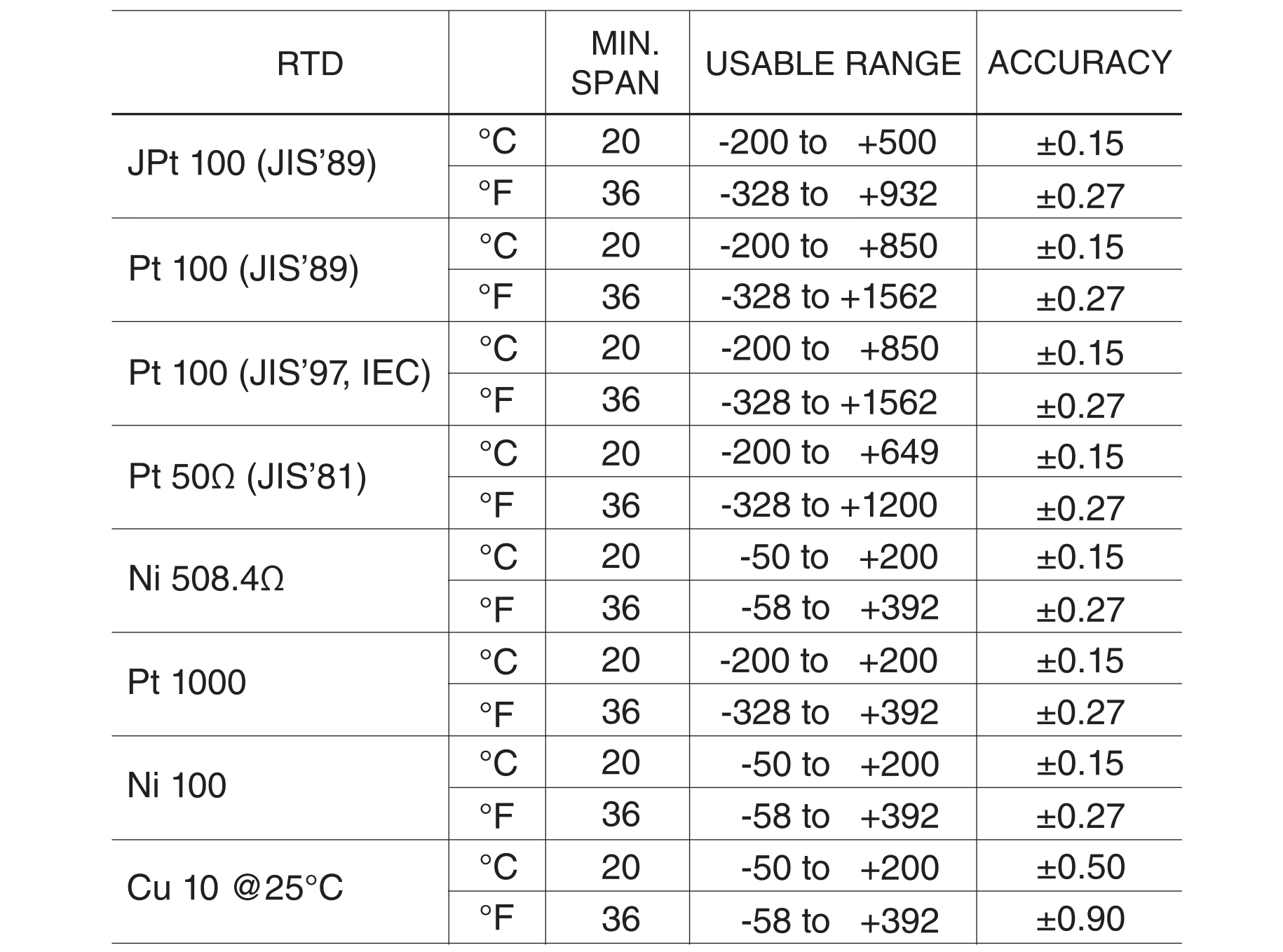
- Dải nhiệt độ: Xem Bảng 1
Nếu không chỉ định, dải mặc định như sau:
- JPt100 (JIS ’89): 0 – 100°C
- Pt100 (JIS ’89): 0 – 100°C
- Pt100 (JIS ’97, IEC): 0 – 100°C
- Pt50 Ω (JIS ’81): 0 – 200°C
- Ni 508.4 Ω: 0 – 100°C
- Pt1000: 0 – 100°C
- Ni100: 0 – 100°C
- Cu10 @25°C: 0 – 100°C
THÔNG SỐ ĐẦU RA
Dòng DC
- Dải hoạt động: 0 – 24 mA DC
- Dải đầu ra: 0 – 20 mA DC
- Span tối thiểu: 1 mA
- Offset: Giá trị thấp có thể cài đặt trong dải cho phép, miễn duy trì span tối thiểu
- Tải: Khả năng cấp tối đa 15 Vc(ví dụ: 4 – 20 mA → 750 Ω [15 V ÷ 20 mA])
- Mặc định: 4 – 20 mA DC
Điện áp DC
Mã V1 (dải hẹp):
- Dải hoạt động: -3 – +3 V DC
- Dải đầu ra: -2.5 – +2.5 V DC
- Span tối thiểu: 250 mV
Mã V2 (dải rộng):
- Dải hoạt động: -11.5 – +11.5 V DC
- Dải đầu ra: -10 – +10 V DC
- Span tối thiểu: 1 V
- Offset: Giá trị thấp có thể cài đặt trong dải cho phép, miễn duy trì span tối thiểu
- Tải: Dòng cấp tối đa 1 mA (ví dụ: 1 – 5 V → 5000 Ω [5 V ÷ 1 mA])
Nếu không chỉ định, dải mặc định:
- V1: 0 – 1 V DC
- V2: 1 – 5 V DC
LẮP ĐẶT
Công suất tiêu thụ
-
AC:
-
~3 VA tại 100 V
-
~4 VA tại 200 V
-
~5 VA tại 264 V
-
-
DC: ~2 W
- Nhiệt độ làm việc: -30 đến +60°C
- Độ ẩm làm việc: 30 – 90 %RH (không ngưng tụ)
- Lắp đặt: Gắn bề mặt hoặc ray DIN
- Trọng lượng: 120 g
HIỆU SUẤT
-
Độ chính xác: Theo Bảng 1 hoặc ±0.1 % span (lấy giá trị lớn hơn)
-
Cộng thêm 0.2 % khi span đầu ra ≤ 1/10 span tối đa
-
-
Hệ số nhiệt: ±0.015 %/°C của span tối đa (-5 đến +55°C)
-
Thời gian đáp ứng: ≤ 0.9 giây (0 – 90 %)
-
Thời gian phản hồi burnout: ≤ 10 giây
-
Ảnh hưởng điện áp nguồn: ±0.1 % trong dải điện áp
-
Điện trở cách điện: ≥ 100 MΩ (500 V DC)
-
Chịu điện áp: 2000 V AC / 1 phút (đầu vào – đầu ra – nguồn – đất)
VÍ DỤ TÍNH TOÁN ĐỘ CHÍNH XÁC TỔNG THỂ
Ví dụ 1
-
Đầu vào: Pt100 (JIS ’97, IEC), 0 – 500°C
-
Đầu ra: 4 – 20 mA DC
- ±0.15°C → 0.15 ÷ 500 = 0.03 %
- 0.03 % ≤ 0.1 % → chọn 0.1 %
- Span đầu ra 16 mA ≥ 1/10 span tối đa → không cộng 0.2 %
- Độ chính xác tổng thể: ±0.1 % span
Ví dụ 2
-
Đầu vào: Pt100 (JIS ’97, IEC), 0 – 100°C
-
Đầu ra: 2.0 – 2.5 V DC
- ±0.15°C → 0.15 %
- 0.15 % ≥ 0.1 % → chọn 0.15 %
- Span đầu ra 0.5 V ≤ 1/10 span tối đa → cộng 0.2 %
- Độ chính xác tổng thể: ±0.35 % span
TIÊU CHUẨN & CHỨNG NHẬN
Phù hợp tiêu chuẩn EU
-
EMC Directive
-
EMI: EN 61000-6-4
-
EMS: EN 61000-6-2
-
-
Low Voltage Directive: EN 61010-1
-
Cấp lắp đặt II
-
Mức ô nhiễm 2
-
Đầu vào/đầu ra với nguồn: Cách điện tăng cường (300 V)
-
Đầu vào với đầu ra: Cách điện cơ bản (300 V)
-
-
RoHS Directive
Chứng nhận
-
UL / C-UL Class I, Division 2
-
Nhóm A, B, C, D
-
(UL 121201, CAN/CSA-C22.2 No.213-17)
-
-
UL / C-UL yêu cầu an toàn chung
-
(UL 61010-1, CAN/CSA-C22.2 No.61010-1-12)
-
Hỗ trợ trực tuyến

Mobile:
Tel:


