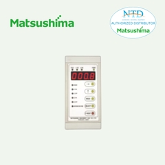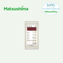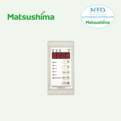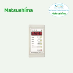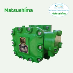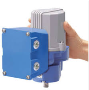
MRP10 STEP-TOP ELECTRONIC ACTUATOR
MRP10
ELECTRONIC ACTUATOR
STEP-TOP ELECTRONIC ACTUATOR
(Rotary type; Modbus communication)
Functions & Features
• Equipped stepping motor for drive motor.
• High-speed operation control (1/1000 high resolution)
• Output stem angle can be certainly adjusted in 0.1° increments
• Both Modbus-RTU communication and analog signal can use
• USB (CONFIG-Type-C), PU-2x jack, and DIP switches
• Equipped manual operation stem and indicator
• Equipped terminal box standardly (LEDs can be visually checked from outside)
Typical Applications
• Actuator for automatic control valve in various plants and industries
• Electronic actuator for fuel cell system and refrigerating machines
MODEL: MRP10–[1][2][3]–[4]CR[5]
ORDERING INFORMATION
• Code number: MRP10-[1][2][3]-[4]CR[5]
Specify a code from below for each of [1] through [5].
(e.g. MRP10-1AA-ACR/Q)
• Specify the specification for option code /Q
(e.g. /C03/SET)
[1] OUTPUT STEM OPERATIONAL ANGLE
1: 90 degrees
[2] OPERATION TORQUE, OPERATION TIME
(90 DEGREES), TORQUE AT LOCK (MAX. VALUE)
[3] INPUT
Current
A: 4 – 20 mA DC (Input resistance 250 Ω)
Voltage
6: 1 – 5 V DC (Input resistance 200 kΩ min.)
[4] OUTPUT
Current
A: 4 – 20 mA DC (Load resistance 300 Ω max.)
Voltage
6: 1 – 5 V DC (Load resistance 5 kΩ min.)
CE & UKCA MARKING
C: With CE and UKCA
POWER SUPPLY VOLTAGE
DC Power
R: 24 V DC
(Operational voltage range 24 V ±10 %, ripple 10 %p-p max.)
[5] OPTIONS
blank: none
/Q: With options (specify the specification)
SPECIFICATIONS OF OPTION: Q (multiple selections)
COATING (For the detail, refer to our web site.)
/C03: Rubber coating
EX-FACTORY SETTING
/SET: Preset according to the Ordering Information Sheet
(No. ESU-4889)
RELATED PRODUCTS
• PC configurator software (model: STCFG)
• Programming Unit (model: PU-2x)
GENERAL SPECIFICATIONS
Degree of protection: IP66
Action: "Reverse" action (switchable with DIP switch to "direct" action.)
Operation at low input:
· Stop at full-open position
· Stop at full-close position
· hold position (ex-factory setting)
Low input signal level
· Current input: ≤ 1.48 (±0.2) mA DC
· Voltage input: ≤ 0.37 (±0.05) V DC
Wiring conduits: G 1/2 female thread and G 3/4 female thread (total four)
Terminal block: 7.62 mm pitch; M3 screw terminals (torque 0.5 N·m)
Screw terminal: Nickel-plated brass (not magnet)
Housing material: Diecast aluminum (ADC12)
Coating: Thermosetting acrylic resin
Coating: Silver color
Drive: Stepping motor
Insulation class: E
Position detection: Conductive potentiometer
Deadband adjustment: 0.1 – 0.5 % (1/1000 to 1/200)
Restart limiting timer adjustment: 0.1 – 5.0 sec.
Isolation: Power voltage or I/O signal to full-open signal position to full-close signal position to alarm signal to Modbus communication to metallic housing
Protective functions
· Automatically stops when torque at lock
· Automatically stops when surface temperature of the stepping motor is over 100°C (212°F) and automatically restarts under 95°C (203°F).
· Automatically heats to +2°C (35.6°F) when surface temperature of the stepping motor is under 0°C (32°F). The motor continues to run.
· A heater is incorporated to use under cold areas.
· Thermostat is incorporated to automatically heat when 27°C (±5°C) (80.6°F (±9°F) or lower, and automatically stop heating when 39°C (±4°C) (102.2°F (±7.2°F)) or higher.
Status Indicator LED
· POWER: Green LED turns on when the power voltage is ON
· INPUT: Green LED turns on with normal input signal
· MOVING UP/CCW.: Green LED turns on when full-open
· MOVING DOWN/CW.: Green LED turns on when full-close
· COM: Green LED turns ON while Modbus communication
· ALARM: Red LED blinks when abnormal operation
(For details, refer to users manual)
User-configurable items:
Configurable with DIP switch
· Stem operation at low input
· Switching direct/reverse
· Switching signal output
· Set full-open position
· Set full-close position
Configurable with PC or PU-2x
· Set full-open position
· Set full-closed position
· Deadband
· Restart limiting timer
· Full-open signal position
· Full-close signal position
· Output stem operation angle
Configurable with Modbus communication
· Input
· Node address
· Baud rate
· Parity bit
· Stop bit length
· Internal terminating resistor
· Loss of Modbus communication detection time
Action: Switching range of reverse/direct (following table)
· Increasing input signal, output stem moves to the full-open side (reverse)
· Increasing input signal, output stem moves to the dull-close side (direct)
MODBUS COMMUNICATION
Communication: Half-duplex, asynchronous, no procedure
Standard: TIA/EIA-485-A compatible
Transmission distance: 500 meters max.
Baud rate: 4800, 9600, 19200, 38400 bps
(ex-factory setting: 38400 bps)
Protocol: Modbus RTU
Node address: 1 to 247 (ex-factory setting: 1)
Parity: None, Odd, Even
Stop bit: 1, 2
Max. number of nodes: 31 (excluding master)
Transmission media: Shielded twisted-pair cable (CPEV-S 0.9 dia.)
Internal terminating resistor: 120 Ω
OUTPUT SPECIFICATIONS
■ Output signal
• 4-20 mA DC or 20-4 mA DC (non-isolated)
Load resistance: 300 Ω max.
• 1-5 V DC or 5-1 V DC (non-isolated)
Load resistance: 5 kΩ min.
■Full-open signal, full-close signal (CCW SIG., CW SIG.)
• Output type: Photo MOSFET relay
• Rated load: 160 V 150 mA AC/DC at peak
• ON resistance: 8 Ω max.
• Leakage current during opening/closing: 2 μA max.
■ Alarm output (triggered when the output stem is locked)
• Output type: Photo MOSFET relay
• Rated load: 160 V 150 mA AC/DC at peak
• ON resistance: 8 Ω max.
• Leakage current during opening/closing: 2 μA max.
STROKE RATE
Duty cycle = Within 50 %
The unit must operate at an average duty cycle of 50% (ratio of operating time to standby time) or less.
Operation rate: Less than 13 strokes / min. (excepting momentary peak stroke rate)
INSTALLATION (POWER VOLTAGE: @ 24 V DC)
Operating temperature: -25 to +66°C (-13 to 150.8°F) (No direct sunlight, radiant heat or heat transfer.)
Storage temperature: -29 to +70°C (-20.2 to 158°F)
Operating humidity: 30 to 90 %RH (non-condensing)
Vibration resistance:
• Sweep endurance test (IEC 61298-3 compliant)
• Acceleration: 19.6 m/s2 (2 G)
• Frequency: 10 to 1000 Hz
• Cycle: 20 cycles
• Sweep rate: 1 oct./min.
• Testing time: approx. 4 hr. 30 min.
• Direction: X, Y, Z
Mounting orientation:
DO NOT mount upside-down
Weight: Approx. 4.4 kg (8.820 lb)
PERFORMANCE
Resolution: 0.1%
Hysteresis: 0.6%
Linear characteristic: 1%
Backlash: 0.3 degrees
Insulation resistance: ≥ 100 MΩ with 500 V DC
(Power voltage or I/O signal to full-open signal to full-close signal to alarm signal to Modbus communication to metallic housing)
Dielectric strength: 500 V AC @ 1 minute (or 600 V AC @ 1 second)
(Power voltage or I/O signal to full-open signal to full-close signal to alarm signal to communication to metallic housing)
STANDARDS & APPROVALS
■ EU conformity (CE marking)
•EMC Directive
EMI EN 61000-6-4
EMS EN 61000-6-2
RoHS Directive
EN IEC 63000
TERMINOLOGY
• Modbus communication
Operation status of the actuator can be monitored during normal operation for ensuring safe operation of the product and supporting equipment maintenance.
Via Modbus communication, the following data can be monitored to grasp the operation status of the actuator.
- No. of times of start actions of the stepping motor
- No. of times of reverse actions of the stepping motor
- Accumulated operating time of the stepping motor
- Accumulated operation angle of the output stem (counts full-open (-close) to full-close (-open) as 1)
- No. of times of restart when an excessive torque error occurs
- Excessive torque error
•Excessive torque monitoring
Function to stop the stepping motor when an excessive torque is detected. Specifically, the unit constantly monitors the position of the output stem while the stepping motor is driven. When the unit detects that the output stem is not following the position detecting value of the potentiometer, tries to operate with set torque at lock. If the output stem does not follow the motor after two times, an error of excessive torque occurs and the stepping motor is stopped (alarm signal). Following methods can release the alarm signal.
- Turn DIP SW 1-8 OFF to ON (Be sure to turn ON to OFF again)
- Turn off the power voltage.
- Input opposite value of the current one
- Set via PU-2x or Modbus communication
• Deadband
Linear resolution
• Hysteresis
The output stem reciprocates i.e. opens and closes according to the input signal.
Hysteresis is the difference between the two curves of ascending and descending directions, which is expressed in percentage.
• Linear Characteristics
The output stem reciprocates i.e. opens and closes according to the input signal. In the case of MRP, the difference between the theoretical value and the actual distance that the output stem actually moved is expressed in percentage.
• Restart Limiting Timer
This function prevents the output stem operates frequently when the input signal is unstable.
To prevent the output stem operates frequently, it does not operate at the moment the input signal changes, but after a set period of time.
TERMINAL CONNECTIONS
COMMUNICATION CABLE CONNECTIONS
EXTERNAL DIMENSIONS unit: mm [inch]
SCHEMATIC CIRCUITRY & CONNECTION DIAGRAM
--------------------


