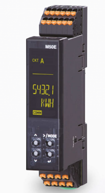

MULTI POWER TRANSDUCER M50EXWTU
M50EXWTU
Terminal Block Signal Conditioners with Display M50E-UNIT
MULTI POWER TRANSDUCER
(PC programmable)
Functions & Features
• Super-mini power transducer
• 5 to 600 A clamp CT use for current sensor
• Single-phase/2-wire, single-phase/3-wire, 3-phase/3-wire and 3-phase/4-wire are available
• Single phase can measure up to four circuits, single-phase/3-wire, Three-phase/2-wire can measure up to two circuits
• High-density mounting
• Organic EL display

MODEL: M50EXWTU-223-AD4[1]
ORDERING INFORMATION
• Code number: M50EXWTU-223-AD4[1]
Specify a code from below for [1].
(e.g. M50EXWTU-223-AD4/Q)
• Specify the specification for option code /Q
(e.g. /C01/SET)
CONFIGURATION
2: Single phase / 2-wire and 3-wire,
3-phase / 3-wire and 4-wire
INPUT
2: 480 V AC / CLSE
Clamp-on current sensor is selectable from below.
CLSE (5 A, 50 A, 100 A, 200 A, 400 A, 600 A)
5 A is available as CT's secondary.
EXTERNAL INTERFACE
3: Modbus communication
POWER INPUT
Universal
AD4: 100 – 240 V AC / 100 – 240 V DC (universal)
(Operational voltage range 85 - 264 V AC, 47 - 66 Hz /
85 - 264 V DC, ripple 10 %p-p max.)
[1] OPTIONS
blank: none
/Q: With options (specify the specification)
SPECIFICATIONS OF OPTION: Q (multiple selections)
COATING (For the detail, refer to our web site.)
/C01: Silicone coating
/C02: Polyurethane coating
/C03: Rubber coating
EX-FACTORY SETTING
/SET: Preset according to the Ordering Information Sheet
(No. ESU-3071)
RELATED PRODUCTS
• PC Configurator cable (model: COP-US)
• PC configurator software (model: PMCFG)
Downloadable at our web site.
• Clamp-on current sensor (model: CLSE)
GENERAL SPECIFICATIONS
Connection: Tension clamp terminal
Applicable wire size:
Lower connector (voltage input, power, Modbus)
0.2 - 1.5 mm2, stripped length 8 - 9 mm
Upper connector (current sensor input, pulse output)
0.2 - 1.5 mm2, stripped length 10 - 11 mm
Housing material: Flame-resistant resin (black)
Isolation: Voltage input or current input to Modbus to pulse output 1 to pulse output 2 to power
Measured variables
Voltage: 1-N, 2-N, 3-N, 1-2, 2-3, 3-1
Current: 1, 2, 3, N
Active power
Reactive power
Apparent power
Power factor
Frequency
Active energy: Incoming / outgoing
Reactive energy: Incoming / outgoing / lag (inductive)
/lead (capacitive)
Harmonic distortion:
Overall distortion ratio, content rate (2nd to 31st)
Max. and min. values
CO2 emissions (energy conversion value)
Simplified measurement mode: Calculates power from current values with fixed voltage values and power factor.
MODBUS COMMUNICATION
Communication: Half-duplex, asynchronous, no procedure
Standard: Conforms to TIA/EIA-485-A
Transmission distance: 500 meters max.
Baud rate: 1200, 2400, 4800, 9600, 19200, 38400 bps (default: 38400 bps)
Protocol: Modbus RTU
Node address: 1 to 247 (default: 1)
Parity: None, even or odd (default: odd)
Stop bit: 1 or 2 (default: 1)
Max. number of nodes: 31 (excluding master)
Transmission media: Shielded twisted-pair cable
(CPEV-S 0.65 to 0.9 dia.)
Internal terminating resistor: 110 Ω
DISPLAY
Display functions: Displays measured value and status of the unit
Display size: Approx. 14 × 40 mm (0.55” × 1.57”)
Character color: Yellow
Brightness: Standard or low brightness (default: standard)
Display life: Approx. 120,000 hours
(Expected time for the Display brightness to be reduced to 50 % when the Display is used continuously with low brightness in 25℃)
Operating mode: Automatically turn off after no operation, or always on
(default: automatically turn off after no operation for 10 minutes)
Display type: OEL display
INPUT SPECIFICATIONS
Frequency: 50 / 60 Hz (45 – 66 Hz)
• Voltage Input
Rated voltage for each wiring:
• Single-phase/2-wire rated voltage 240 V AC
• Single-phase/3-wire phase voltage 240 V AC / line voltage 480 V AC
• Three-phase/3-wire line voltage 240 V AC
(480 V AC when voltage to ground for each line is ≤ 277 V)
• Three-phase/4-wire phase voltage 277 V / line voltage 480 V AC
Input range: 1-N, 2-N, 3-N 50 to 277 V AC
1-2, 2-3, 3-1 50 to 480 V AC
Consumption VA: Voltage circuit ≤ ULN2 / 250 kΩ / ph
Selectable primary voltage range: 50 – 400 000 V
• Current Input
Current sensor (default: CLSE-R5)
CLSE-R5: 0 – 5 A AC
CLSE-05: 0 – 50 A AC
CLSE-10: 0 – 100 A AC
CLSE-20: 0 – 200 A AC
CLSE-40: 0 – 400 A AC
CLSE-60: 0 – 600 A AC
Input range: 0 - 120 % of the rating
Low-end cutout (current): 0 - 99.9 % (default setting: 1 %)
Selectable primary current range: 1 – 20 000 A (only with CLSE-R5, refer to the configurator settings)
OUTPUT SPECIFICATIONS
■Pulse output
Outputs assignable to pulse: various energy
Output type: Photo MOSFET relay
Rated load: 30 V 200 mA AC/DC at peak
ON resistance: 1 Ω max.
Leakage current during opening: 2 μA max.
INSTALLATION
Power consumption
•AC: ≤ 3 VA
•DC: ≤ 1.5 W
Operating temperature: -20 to +65°C (-4 to +149°F)
Operating humidity: 30 to 90 %RH (non-condensing)
Mounting: DIN rail
Weight: 90 g (0.2 lb)
PERFORMANCE
Accuracy*1
Voltage: ±0.5 %*2
Current: ±0.5 %*2
Power: ±0.5 %*2
Power factor: ±1.5 %
Frequency: ±0.1 Hz
Energy: ±2 % (power factor ≥ 0.5, input ≥ 10 %)
*1. Sensor error margin not included. Add sensor error margin when using with the combination of the sensor.
*2. The described accuracy levels are ensured at the input 1 % or more for neutral current in a single-phase/3-wire circuit, phase-2 current in a 3-phase/3-wire circuit and phase-N current in a 3-phase/4-wire circuit.
Temp. coefficient: ±0.0075 %/°C (0.004 %/°F)
Sampling time: ≤ 500 msec.
Insulation resistance: ≥ 100 MΩ with 500 V DC
Dielectric strength: 2000 V AC @ 1 minute
(current input or voltage input to Modbus to pulse output 1 or pulse output 2 to power)
500 V AC @ 1 minute (pulse output 1 to pulse output 2)
STANDARDS & APPROVALS
EU conformity:
EMC Directive
EMI EN 61000-6-4
EMS EN 61000-6-2
Low Voltage Directive
EN 61010-1
Measurement Category II (input)
Installation Category II (power supply)
Pollution Degree 2
Voltage input to current input or Modbus or pulse output:
Reinforced insulation (300 V)
Power to current input or Modbus or pulse output:
Reinforced insulation (300 V)
RoHS Directive
--------------------
CÔNG TY CỔ PHẦN KỸ THUẬT VÀ THƯƠNG MẠI THIẾT BỊ CÔNG NGHIỆP NTD
Adress: No. 28, Alley 36 Co Linh Street, Group 7, Long Bien Ward, Long Bien District, Hanoi City, Vietnam.
Hotline: 0971961212
Mail: sales@ntd-automation.com
Hỗ trợ trực tuyến

Mobile:
Tel:


