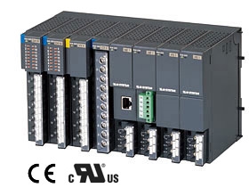
R3 Series - Multi-channel, Mixed Signal Remote I/O
R3 Remote I/O R3 Series
R3 SERIES GENERAL SPECIFICATIONS
Functions & Features
• Free combination of analog and discrete I/O
• Various open field bus (DeviceNet, Modbus, etc.)
• Direct sensor inputs
• Dual redundancy in communication
Typical Applications
• Remote I/O for DCS and PLC
• Personal computer I/O
ORDERING INFORMATION
Refer to the specifications of each module for details.
• Options are available for each model of R3-x, (except R3-DM). Refer to the data sheets of each model for detail.
NETWORK INTERFACE MODULE: R3-[1]-[2]
Refer to the specifications of each module for details.
[1] MODULE TYPE
NC1: CC-Link (Ver. 1.10; 16-point analog)
NC2: CC-Link (Ver. 1.10; 32-point analog)
NC3: CC-Link (Ver. 2.00)
NCIE1: CC-Link IE Field network
(Power input code not selectable)
ND1: DeviceNet (16-point analog)
ND2: DeviceNet (32-point analog)
ND3: DeviceNet (64-point analog)
NE1: Ethernet (Modbus/TCP)
NEIP1: EtherNet/IP
(Power input code not selectable)
NF1: T-Link (Fuji Electric)
NF2: T-Link (Fuji Electric T-Link interface module equivalent)
NF3: T-Link (Fuji Electric T-Link capsule equivalent)
(Power input code K3, L3 not selectable)
NFL1: FL-net (Ver. 2.0; OPCN-2)
(Power input code not selectable)
NM1: Modbus
NM3: Modbus
(Temperature control module supported)
NM4: Modbus (for 115.2 kbps)
(Power input code K3, L3 not selectable)
NML3: MECHATROLINK-Ⅲ(MECHATROLINK-Ⅲ)
NP1: PROFIBUS-DP
NL1: LonWorks (analog I/O 16 points, discrete I/O 48 points)
NL2: LonWorks (I/O 56 points)
NMW1F: For Modbus Wired Communication, 900 MHz Band Devices
(Power input codes K3 and L3 not selectable)
(For use in U.S. only)
[2] POWER INPUT
N: No power supply
AC power
M2: 100 - 240V AC
(Selectable only for module type NF3, NM4 and NMW1F)
K3: 100 – 120 V AC
L3: 200 – 240 V AC
DC power
R: 24 V DC
INTERFACE I/O MODULE: R3-[1]S
Refer to the specifications of each module for details.
[1] MODULE TYPE
GC1: CC-Link (Ver. 1.10/ Ver. 2.00)
GD1: DeviceNet
GE1: Ethernet (Modbus/TCP)
GFL1: FL-net (Ver. 2.0; OPCN-2)
GM1: Modbus
COMMUNICATION MODE
S: Single
BASE: R3-[1][2]
Refer to the specifications of each base for details.
[1] MODULE TYPE
BS: Base
BSW: Base, free I/O address
[2] NUMBER OF SLOTS
02: 2 slots (R3-BS only)
02P: 2 slots (R3-NP1 only)
(R3-BS only)
04: 4 slots
06: 6 slots
08: 8 slots
10: 10 slots
12: 12 slots
14: 14 slots
16: 16 slots
I/O MODULE: R3-[1][2]
Refer to the specifications of each module for details.
[1] MODULE TYPE
• Analog Input
SS4: DC current input, 4 ch.
SS8: DC current input, 8 ch.
SS8N: DC current input, 8 ch., non-isolated
SS16N: DC current input, 16 ch., non-isolated
SV4: DC voltage input, 4 ch.
SV4A: DC voltage input, 4 ch., narrow span
SV4B: DC voltage input, 4 ch., wide span
SV4C: DC voltage input, 4 ch., wide span up to ±50 V
SV8: DC voltage input, 8 ch.
SV8A: DC voltage input, 8 ch., narrow span
SV8B: DC voltage input, 8 ch., wide span
SV8C: DC voltage input, 8 ch., wide span up to ±50 V
SV8N: DC voltage input, 8 ch., non-isolated
SV16N: DC voltage input, 16 ch., non-isolated
TS4: Thermocouple input, 4 ch.
TS8: Thermocouple input, 8 ch.
TS8A: Thermocouple input, 8 ch., high accuracy
RS4: RTD input, 4 ch.
RS4A: RTD input, 4ch., high accuracy
RS8: RTD input, 8 ch.
RS8A: RTD input, 8 ch., high accuracy
RS8B: RTD input, 8 ch., ultra-high accuracy
MS4: Potentiometer input, 4 ch.
MS8: Potentiometer input, 8 ch.
DS4: 4 – 20 mA input w/exc., 4 ch.
DS4A: 4 – 20 mA input w/exc. (switch provided), 4 ch.
DS8N: 4 – 20 mA input w/exc., 8 ch., non-isolated
CT4: CT (AC current) input, 4 ch.
CT4A: AC current input, 4 ch., clamp-on current sensor CLSA use
CT4B: AC current input, 4 ch., clamp-on current sensor CLSB use
CT4C: AC current input, 4 ch., clamp-on current sensor CLSB-R5 use
CT8A: AC current input, 8 ch., clamp-on current sensor CLSA use
CT8B: AC current input, 8 ch., clamp-on current sensor CLSB use
CT8C: AC current input, 8 ch., clamp-on current sensor CLSB-R5 use
PT4: PT (AC voltage) input, 4 ch.
CZ4: Zero-phase current input, 4 ch.
WT1: Multi-power input, 1 circuit
WT1A: Multi power input, 4 ch., clamp-on current sensor CLSA use
WT1B: Multi power input, 4 ch., clamp-on current sensor CLSB use
WT4: AC power input, 4 points
WT4A: AC power input, 4 ch., clamp-on current sensor CLSA use
WT4B: AC power input, 4 ch., clamp-on current sensor CLSB use
WTU: AC power input, 2 ch., clamp-on current sensor CLSE use
(Communication Mode ‘S’ only)
LC2: Strain gauge input, 2 ch.
US4: Universal input, 4 ch.
TC2: Temperature Control
(Only communication mode 'S' selectable)
MEX2: Valve Positioner
(for 2 systems; built-in SSR)
• Analog Output
YV4: DC voltage output, 4 ch.
YV8: DC voltage output, 8 ch.
YS4: DC current output, 4 ch.
• Pulse Input
PA2: Encoder input, 2 ch. (speed and position)
PA4: High speed pulse input, 4 ch.
PA4A: High speed totalized pulse input, 4 ch.
PA4B: Low speed totalized pulse input, 4 ch.
PA8: Totalized pulse input, 8 ch.
PA16: Totalized pulse input, 16 ch.
• Pulse Output
PC16A: Pulse output, 16 ch.
PD16: One-shot pulse output 16 ch. (Relay)
PD16A: One-shot pulse output 16 ch. (NPN)
PD16B: One-shot pulse output 16 ch. (Triac)
PD16C: One-shot pulse output 16 ch. (PNP)
• Discrete Input
BA32A: BCD input (ext. 24 V DC)
DA16: Optical isolation discrete input, 16 ch. (13 V DC)
DA16A: Optical isolation discrete input, 16 ch.
DA16B: Optical isolation discrete input, 16 ch. (ext. 100 V AC)
DA32A: Optical isolation discrete input, 32 ch.
DA64A: Optical isolation discrete input, 64 ch.
DA8C: Optical isolation discrete input, 8 ch. (3-wire)
• Discrete Output
BC32A: BCD output (open collector)
DC16: Relay output, 16 ch.
DC16A: Open collector output, 16 ch. (NPN)
DC16B: Triac output, 16 ch.
DC16C: Open collector output, 16 ch. (PNP)
DC32A: Open collector output, 32 ch.
DC32C: Open collector output, 32 ch.
(PNP transistor output, shortcircuit protection)
DC64A: Open collector output, 64 ch.
DC64C: Open collector output, 64 ch.
(PNP transistor output, shortcircuit protection)
DC8: Relay contact output, 8 ch.
DC8D: Photo MOSFET relay output, 8 ch.
RR8: Remote control relay control, 8ch.
• Discrete I/O
DAC16: Discrete I/O (Di 8 ch., Do 8 ch.)
DAC16A: Discrete I/O (Di 8 ch., Do 8 ch., internal power)
• Alarm
AS4: DC current input alarm, 4 ch.
AS8: DC current input alarm, 8 ch.
AV4: DC voltage input alarm, 4 ch.
AV8: DC voltage input alarm, 8 ch.
AT4: Thermocouple input alarm, 4 ch.
AR4: RTD input alarm, 4 ch.
AD4: 4 – 20 mA input alarm w/exc., 4 ch.
[2] COMMUNICATION MODE
S: Single
W: Dual
I/O MODULE WITH CONNECTOR TERMINAL: R3Y-[1][2]
Refer to the specifications of each module for details.
[1] MODULE TYPE
• Analog I/O (FCN connector)
SS8: DC current input, 8 ch.
SS8N: DC current input, 8 ch., non-isolated
SS16N: DC current input, 16 ch., non-isolated
SV8: DC voltage input, 8 ch.
SV8A: DC voltage input, 8 ch., narrow span
SV8N: DC voltage input, 8 ch., non-isolated
SV16: DC voltage input, 16 ch., non-isolated
YV8: DC voltage output, 8 ch.
YS4: 4 – 20 mA output, 4 ch.
RS8: RTD input, 8 ch.
MS8: Potentiometer input, 8 ch.
DS4: 4 – 20 mA input, 4 ch. excitation supply
DS8N: 4 – 20 mA input, 8 ch. excitation supply, non-isolated
• Pulse I/O (FCN connector)
PA16: Totalized pulse input, 16 ch.
• Discrete I/O (FCN connector)
DA16: Optical isolation discrete input, 16 ch. (13 V DC)
DA16A: Optical isolation discrete input, 16 ch. (ext. 24 V DC)
DC16: Relay output, 16 ch.
DAC16D: Optical isolation discrete input, 8 ch. (internal power),
photo MOSFET relay output, 8 ch.
[2] COMMUNICATION MODE
S: Single
W: Dual
I/O MODULE: R3S-[1][2]
Refer to the specifications of each module for details.
[1] MODULE TYPE
• Analog I/O (Separable tension clamp terminal)
SS8N: DC current input, 8 ch., non-isolated
SV8N: DC voltage input, 8 ch., non-isolated
YV4: DC voltage output, 4 ch., isolated
YS4: DC current output, 4 ch., isolated
RS4A: RTD input, 4 ch., high accuracy
• Pulse input (Separable tension clamp terminal)
PA8: Totalized pulse input, 8 ch., 32 Bits
• Discrete I/O (Separable tension clamp terminal)
DA16: Optical isolation discrete input, 16 ch. (13 V DC)
DC8: Relay contact output, 8 ch.
DAC16: Discrete I/O (Di 8 ch., Do 8 ch.)
DAC16A: Discrete I/O (Di 8 ch., Do 8 ch., internal power)
RR8: Remote control relay control, 8ch.
[2] COMMUNICATION MODE
S: Single
W: Dual
POWER SUPPLY MODULE: R3-[1]-[2]
Refer to the specifications of each module for details.
[1] MODULE TYPE
PS1: Power Supply Module, single slot
(Continuous output current: 750 mA @ 20 V DC)
(Power input code K3 and L3 are not selectable)
PS3: Power Supply Module, double slot
(Continuous output current: 2.0 A @ 20 V DC)
[2] POWER INPUT
• AC power
K: 85 – 132 V AC
K3: 100 - 120 V AC (Selectable only for module type code PS3)
L: 170 – 264 V AC
L3: 200 - 240 V AC (Selectable only for module type code PS3)
• DC power
R: 24 V DC
P: 110 V DC
BLANK FILLER MODULE: R3-[1]
Refer to the specifications of each module for details.
[1] MODULE TYPE
DM: Blank filler module
DESCRIPTIONS
■ GENERAL
The Remote I/O R3 Series consists of power supply module(s), network interface module(s), I/O module(s) and a backplane (base) in free combinations.
Basically, each module only requires DIP switch setting before it is installed.
A large variety of network and I/O modules can be selected to suit many different field applications.
• Power Supply Module
Converts AC or DC power inputs for use in the network modules and I/O modules, and for exciting discrete I/O.
• Network Module
Converts data between the open network fieldbus (Device-Net, etc.) and the internal communication bus, functioning as a Gateway between the two buses.
• Interface I/O Module
Works as a gateway to handle data on the open network fieldbus (Device-Net, etc.) with different protocol interface module.
• I/O Module
Performs: A/D conversion of field analog inputs; and D/A conversion of data received through the internal bus into analog/discrete outputs.
Single and dual communication modes are selectable.
• Base
Backplane with two independent communications buses and a power supply bus.
• Blank Filler Module
Used to install for unused slots.
■ SINGLE COMMUNICATION MODE
When the single communication mode is employed, the network module receives data from the field bus and sends it to analog/discrete output modules through the internal bus.
The output modules convert the data into analog or discrete outputs.
The input modules send out via the internal bus analog or discrete inputs to the network module. The network module outputs the data to the field bus.
■ DUAL COMMUNICATION MODE
A dual redundant communication system can be easily achieved by employing two network modules and using dual communication type I/O modules (model suffix code ‘W’).
Each I/O module is equipped with two independent communication ports, which are connected to the separate network modules. In normal conditions, output modules receive data from both network modules and output the signal from the preferred communication bus A.
When an error is detected in the fieldbus wiring, network module, or in the internal bus (comm. time error, data error, etc.), the output is switched to the data from the communication bus B. The bus A is checked and automatically back for use if it is in normal conditions.
If both are in error, the output modules hold the signal and stand by until one of the communications recovers. (The output could be turned to OFF by setting.)
Input modules continuously respond to request-to-send from the both lines. This secures two independent communications.
■ HOT SWAPPABLE I/O MODULES
Each I/O and network module has an independent CPU. Data is renewed by serial communications between modules. Therefore no momentary lapse or bumping of analog output occurs when switching communication buses in the dual communication mode.
Furthermore, removing or replacing modules does not adversely affect other modules on the same backplane. It is possible to replace them without removing the power supply.
However, replacing multiple modules at once may greatly change line voltage levels. We highly recommend to replace them one by one.
In order to avoid communication malfunction, mount modules as quickly and securely as possible.
RELATED PRODUCTS
• PC configurator software (model: R3CON)
Downloadable at M-System’s web site.
A dedicated cable is required to connect the module to the PC. Please refer to the internet software download site or the users manual for the PC configurator for applicable cable types.
GENERAL SPECIFICATIONS
Connection: Refer to the specifications of each module.
Housing material: Flame-resistant resin (gray)
■ INTERNAL COMMUNICATION BUS
The read rate is of approx. 6 msec. per I/O module. Total communication cycle is multiplied by the number of I/O module.
■ DATA CONVERSION
Varies depending on the types of I/O modules. Refer to the specifications of the respective I/O modules for details.
• Percent Data
The scaled input range of 0 – 100 % is converted into hexadecimal 0000 – 2710 (0 – 10000). The operational range is from -15 to +115% of the input range. When the signal exceeds the lower or upper limit of the operational range, the data is fixed at -15% or +115%. Negative value is represented in 2’s complements. The same applies to DC voltage or current output.
Note: The signal will remain within the operational range depending on the scaled 0% and 100% input values.
• Engineering Unit Data: Temperature
Temperature input (T/C or RTD) is converted into signed binary data which equals 10 times its engineering unit value (°C). For example, 25.5°C is converted into 255. For °F temperature unit, the integer part of raw data is directly adopted. That is, 135.4°F is converted into 135. Minus temperature is converted into negative value represented in 2’s complements.
(For R3-TS8A, R3-RSxA, R3-RSxB, temperature input is converted into signed binary data which equals 100 times its engineering unit value.)
• Engineering Unit Data: Clamp-on Current Sensor (Except R3-CTxC)
AC input from a clamp-on current sensor is converted into signed binary data which equals 100 times its engineering unit value (A). For example, 10 A is converted to 1000. The operational range is from 0 to +115% of the input range. When the signal exceeds the upper limit of the operational range, the data is fixed at +115%. No negative value is available.
Note 1: Percent data for R3-CTxC.
Note 2: The signal will not exceed +115% depending on the scaled 100% input value.
■ ZERO & SPAN SCALING
The network module inputs or outputs the internal conversion data by the preset scale.
INSTALLATION
Operating temperature: -10 to +55°C (14 to 131°F)
Operating humidity: 30 to 90 %RH (non-condensing)
Atmosphere: No corrosive gas or heavy dust
Mounting: Surface or DIN rail
CURRENT CONSUMPTION
DATA IN ABNORMALITIES
■ NETWORK MODULES
Input signal behaviour in case of input module abnormalities (when the internal transmission between the input module and network module is lost) can be defined by setting DIP switches on the network module.
• Input Hold
Last input signals are held until a normal data is received.
• Set to ‘0’
The network module holds the data at ‘0’ until a normal data is received.
■ OUTPUT MODULES
Field output behaviour in case of transmission abnormalities (when the output data is not updated within the predefined time period) can be defined by setting DIP switches on the output module.
• Output Hold
Last output signals are held until a normal data is received.
• Output OFF
Analog output modules hold the output signals at -15 %, and discrete output modules turns the output to OFF until a normal data is received.
BASIC CONFIGURATIONS
EXTERNAL DIMENSIONS unit: mm (inch)
MOUNTING REQUIREMENTS unit: mm (inch)
CONFORMITY WITH CE MARKING
■ CE MARKING
CE marking requires to integrate safety regulations existed in each country in EU territory and to secure smooth distribution of products of which safety is guaranteed. It is mandatory by law that products distributed and sold in EU territory to have CE mark which shows that the product conforms with the requirements of EU Directive. Each EU Directive describes the scope of apparatuses to which that EU Directive is applied. This product must conform with EMC Directive.
Each Directive states only basic requirements. In order to mark the CE on an assembled machinery equipment, its manufacturer needs to check the overall conformity with Directives applicable to it.
■ WARNINGS AND CAUTIONS WHEN INSTALLTING
This product needs to be installed in a control panel. This is effective not only to ensure general safety but also to contain noise emissions by this product inside the control panel. We conduct a series of testing to see that the product conforms to EMC Directive while it is installed in the control panel.
Warning and cautions when installing are stated below.
• Use control panels with an internal panel plate, both made of metal, when installing.
• Make sure to adequately ground the control panel and the internal panel plate with a thick cable to maintain low impedance at high frequency.
• Use shielded cables for the signals taken out of the control panel.
• Choose a thick and short cable to ground the FG terminal of the Power Supply Module(s) and the Network Module(s) to the internal panel plate of the control panel.
Note: If electromagnetic radiation disturbance increases by grounding the FG terminal, remove the grounding.
• When painting the internal plate of the control panel, apply masking to expose metal surface to secure conductivity at the sections where the following parts are attached:
- Bolts attaching the internal panel to the control panel
- Ground for the FG of the Power Supply Module(s) and the Network Module(s)
- Earth clamp on the shielded cable
• Noise emissions inside the control panel might leak through its openings. Design them as small as possible. Recommended diameter is 10 cm or less.
Supplement:
Additional measures may be taken depending upon actual installation sites. These points of cautions are illustrated below.
• Prevent noise leakage by wrapping cables using shield covers, shield tubes and flexible conduits etc. if noise leaks through the cable outlet.
• Use an electromagnetic shield gasket and block up the gap between the control panel cabinet and its cover, if noise leaks through it.
• Connecting the internal panel plate and the cover of the control panel to the main cabinet using an earth strap may be effective to strengthen the grounding.
• Electromagnetically shielded control panel cabinet is effective for shielding.
M-System Vietnam


