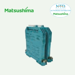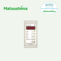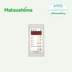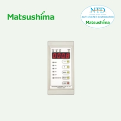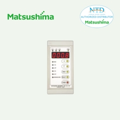
R5-MS1A POTENTIOMETER INPUT MODULE
Remote I/O R5 Series
POTENTIOMETER INPUT MODULE
(re-transmitted output)
MODEL: R5–MS1A[1][2]
ORDERING INFORMATION
• Code number: R5-MS1A[1][2]
Specify a code from below for each of [1] and [2].
(e.g. R5-MS1AW/Q)
• Specify the specification for option code /Q
(e.g. /C01)
NO. OF CHANNELS
1: 1 channel
OUTPUT
Current
A: 4 – 20 mA DC (Load resistance 600 Ω max.)
[1] COMMUNICATION MODE
S: Single
W: Dual
[2] OPTIONS
blank: none
/Q: With options (specify the specification)
SPECIFICATIONS OF OPTION: Q
COATING (For the detail, refer to our web site.)
/C01: Silicone coating
/C02: Polyurethane coating
/C03: Rubber coating
GENERAL SPECIFICATIONS
Connection
Internal bus: Via the Installation Base (model: R5-BS)
I/O: Euro type connector terminal
(Applicable wire size: 0.2 – 2.5 mm2 (AWG24 - 12),
stripped length 7 mm)
Internal power: Via the base (model: R5-BS)
Isolation: Input to output to internal bus or internal power
Zero/Span adj. mode selector: Rotary switch; monitor mode, adj. mode and simulated output mode selectable
RUN indicator: Bi-color (red/green) LED;
Red when the bus A operates normally;
Green when the bus B operates normally;
Amber when both buses operate normally.
INPUT SPECIFICATIONS
Total resistance: 100 Ω – 10 kΩ
Minimum span: 50 % of the total resistance range
Excitation: 0.5 V DC
OUTPUT SPECIFICATIONS
Operational range: Approx. 0 – 24 mA DC
INSTALLATION
Operating temperature: -10 to +55°C (14 to 131°F)
Operating humidity: 30 to 90 %RH (non-condensing)
Atmosphere: No corrosive gas or heavy dust
Mounting: Installation Base (model: R5-BS)
Weight: 100 g (0.22 lb)
PERFORMANCE
Conversion accuracy
Input: ±0.1 %
Output: ±0.1 % of the retransmitted range + input conversion accuracy
Data range: 0 – 10000 of the input range
Data allocation: 1
Temp. coefficient
Input: ±0.015 %/°C (±0.008 %/°F)
Output: ±0.02 %/°C (±0.01 %/°F)
Resolution: 1/10000 of the total resistance range
(Reduced by the actual range determined zero/ span positions. Minimum 50 % of the total resistance range must be maintained.)
Response time: ≤ 0.2 sec. (0 – 90 %)
Insulation resistance: ≥ 100 MΩ with 500 V DC
Dielectric strength: 1500 V AC @ 1 minute (input to output to internal bus or internal power)
2000 V AC @ 1 minute (power input to FG; isolated on the power supply module)
STANDARDS & APPROVALS
EU conformity:
EMC Directive
EMI EN 61000-6-4
EMS EN 61000-6-2
RoHS Directive
FUNCTIONS
• Zero/Span Adjustment Modes
Monitor Mode
Re-transmits the input signal as output in proportion.
Input 0 % Adjustment Mode
Adjusts the 0% input signal. Press the UP button to set.
Input 100 % Adjustment Mode
Adjusts the 100 % input signal. Press the UP button to set.
Output 0 % Adjustment Mode
Adjusts the 0 % output signal using the UP/DOWN buttons, in monitoring the output value with a multimeter.
SW1 through SW3 switch the internal increments by 1, 5 and 10.
Output 100 % Adjustment Mode
Adjusts the 100 % output signal using the UP/DOWN buttons, in monitoring the output value with a multimeter.
SW4 through SW6 switch the internal increments by 1, 5 and 10.
Simulated Output Mode
Outputs the simulated signals of 0 %, 50 % and 100 %.
• How to Operate
1) Start up in Monitor Mode (SW position = 0) and wait for 2 or 3 seconds.
2) Switch to another mode and go through the adjustments.
3) Reset the switch to the position ‘0’ so that the new setting is stored in the internal memory.


