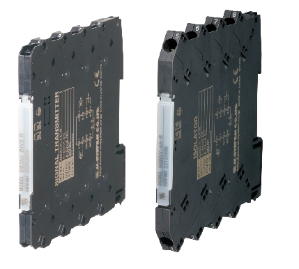

M6SXR (Tension-Clamp Type) RTD input, PC programmable, ultra-slim
M6SXR Tension-Clamp Ultra-Slim Signal Conditioners M6S Series
RTD TRANSMITTER
(PC programmable)
Functions & Features
• Maintenance-free tension clamp connection
• 5.9-mm wide ultra-slim design
• Low profile allows the M6S module mounted in a 120-mm deep panel
• Accepts direct input from an RTD and provides an isolated, linearized DC signal
• Linearization and burnout protection
• PC programmable
• High-density mounting
• Power indicator LED
MODEL: M6SXR–[1][2]–R[3]
ORDERING INFORMATION
• Code number: M6SXR-[1][2]-R[3]
Specify a code from below for each [1] through [3].
(e.g. M6SXR-4Z1-R/UL/Q)
• Temperature range (e.g. 0 – 100°C)
• Output range (e.g. 4 – 20 mA DC)
• Specify the specification for option code /Q
(e.g. /C01/SET)
[1] INPUT RTD
1: JPt 100 (JIS'89)
(Usable range: -200 to +500°C, -328 to +932°F; min.span: 20°C, 36°F)
3: Pt 100 (JIS'89)
(Usable range: -200 to +650°C, -328 to +1202°F; min.span: 20°C, 36°F)
4: Pt 100 (JIS'97, IEC)
(Usable range: -200 to +850°C, -328 to +1562°F; min.span: 20°C, 36°F)
5: Pt 50 Ω (JIS'81)
(Usable range: -200 to +649°C, -328 to +1200°F; min.span: 20°C, 36°F)
7: Pt 1000
(Usable range: -200 to +850°C, -328 to +1562°F; min.span: 20°C, 36°F)
9: Cu 10 @25°C
(Usable range: -50 to +250°C, -58 to +482°F; min.span: 20°C, 36°F)
0: Specify (Please provide a resistance table.)
(Configurator software is used to change the input type and range.
Input code 7, 0 cannot be switched to/from other input types while its temperature range can be changed. It is not available to switch from input code 1, 3, 4, 5, and 9 to '7' or '0'. Be aware above.)
[2] OUTPUT
Current
Z1: Range 0 – 20 mA DC
Voltage
V2: Range -10 – +10 V DC
V3: Range -5 – +5 V DC
(Configurator software is used to change output over the described range of the selected suffix code.
For changing between suffix codes, set the Output Range Selector on the side of unit before software adjustment.)
POWER INPUT
DC Power
R: 24 V DC
(Operational voltage range 24 V ±10 %, ripple 10 %p-p max.)
[3] OPTIONS (multiple selections)
Standards & Approvals
blank: CE marking
/UL: UL approval, CE marking
Other Options
blank: none
/Q: Option other than the above (specify the specification)
SPECIFICATIONS OF OPTION: Q (multiple selections)
COATING (For the detail, refer to M-System's web site.)
/C01: Silicone coating
/C02: Polyurethane coating
EX-FACTORY SETTING
/SET: Preset according to the Ordering Information Sheet
(No. ESU-7833)
RELATED PRODUCTS
• PC configurator software (model: M6CFG)
Downloadable at M-System’s web site.
A dedicated cable is required to connect the module to the PC. Please refer to the internet software download site or the users manual for the PC configurator for applicable cable types.
GENERAL SPECIFICATIONS
Connection
Input and output: Tension clamp
Power input: Via the Installation Base (model: M6SBS)
or Tension clamp
Applicable wire size: 0.2 to 2.5 mm2, stripped length 8 mm
Housing material: Flame-resistant resin (black)
Isolation: Input to output to power
Overrange output: -2 – +102 %
(Negative current output is not available.)
Zero adjustment: -2 to +2 % (PC programming)
Span adjustment: 98 to 102 % (PC programming)
Burnout: Upscale standard; downscale or no burnout optional by programming
Linearization: Standard
Power LED: Green light turns on when the power is supplied.
Status indicator LED: Orange LED; Blinking patterns indicate different operating status of the transmitter.
Programming: Downloaded from PC; input type and range, output type and range, zero and span, burnout type, user’s linearization table, sensor wires, temperature unit, response characteristics (version 1.30 or later), filter time constant, etc.
For detailed information on the For detailed information, refer to the users manual for the PC configurator.
Configurator connection: 2.5 dia. miniature jack;
RS-232-C level
INPUT SPECIFICATIONS
Input: 2-, 3- or 4-wire RTD
Maximum leadwire resistance: 10 Ω per wire
Sensing current; ≤ 1.5 mA
(≤ 0.15 mA for input code 7: Pt 1000 or code 0
Specified maximum resistance in the table > 500 Ω)
Resistance range:
0 - 500 Ω (Input code: 1, 3, 4, 5, 9)
0 - 5 kΩ (Input code: 7)
If not specified, the input range is 0 – 100°C.
OUTPUT SPECIFICATIONS
■ DC Current
Output range: 0 – 20 mA DC
Conformance range: 0 – 20.4 mA DC
Minimum span: 1 mA
Offset: Lower range can be any specific value within the output range provided that the minimum span is maintained.
Load resistance: Output drive 11 V max.
(e.g. 4 – 20 mA: 550 Ω [11 V ÷ 20 mA])
If not specified, the output range is 4 – 20 mA DC.
■ DC Voltage
Code V2 (wide spans)
Output range: -10 – +10 V DC
Conformance range: -10.4 – +10.4 V DC
Minimum span: 1 V
Code V3 (narrow spans)
Output range: -5 – +5 V DC
Conformance range: -5.2 – +5.2 V DC
Minimum span: 0.5 V
Offset: Lower range can be any specific value within the output range provided that the minimum span is maintained.
Load resistance: Output drive 1 mA max.
(e.g. 1 – 5 V: 5000 Ω [5
Hỗ trợ trực tuyến

Mobile:
Tel: