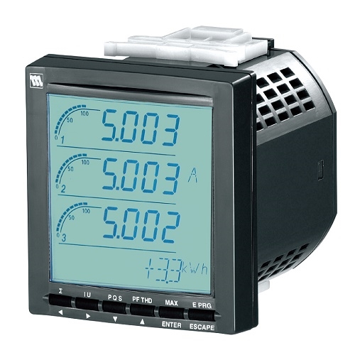
54UC MULTI POWER MONITOR
Power Transducer Series
MULTI POWER MONITOR
(4 digital displays, CC-Link)
Functions & Features
• Measures simultaneously several variables of a heavy-current power system: current, voltage, active, reactive and apparent power, active and reactive energy, power factor, frequency, etc.
• All measured values, counter values, display mode, setting data are stored in the non-volatile memory at the power off
• Parameters are programmable using the front buttons or the PC via infrared interface
• Mounted using M5 screws or mounting brackets
• 60-segment bargraph
• Displayed measurands are freely selectable
• Open collector output for alarm or energy count
• Loop test output
Typical Applications
• Multi-functional power monitor incorporated in an electric device: saves space, wiring works, and cost
MODEL: 54UC-[1][2][3][4]-AD4[5]
ORDERING INFORMATION
• Code number: 54UC-[1][2][3][4]-AD4[5]
Specify a code from below for each of [1] through [5].
(e.g. 54UC-1211-AD4/E/Q)
• Specify the specification for option code /Q
(e.g. /C01/S01)
[1] CONFIGURATION
1: Single phase / 2-wire and 3-wire, 3-phase / 3-wire
2: Single phase / 2-wire and 3-wire,
3-phase / 3-wire and 4-wire
[2] INPUT
1: 480 V / 1 A AC
2: 480 V / 5 A AC
[3] DISCRETE INPUT
0: None (‘External Interface’ code 1 Not selectable.)
1: 24V DC ('External Interface' codes 2 Not selectable.)
2: 110V DC ('External Interface' codes 2 Not selectable.)
[4] EXTERNAL INTERFACE
1: CC-Link, Do × 1, Di × 1
2: CC-Link, Do × 2
AUXILIARY POWER SUPPLY
AD4: universal
100 – 240 V AC (Operational range 85 – 264 V, 50 / 60 Hz) /
110 – 240 V DC (Operational range 99 – 264 V,
ripple 10 %p-p max)
[5] OPTIONS (multiple selections)
Language
blank: Japanese
/E: English
Other Options
blank: none
/Q: Option other than the above (specify the specification)
SPECIFICATIONS OF OPTION: Q (multiple selections)
COATING (For the detail, refer to our web site.)
Moving parts and indicators are not coated.
/C01: Silicone coating
/C02: Polyurethane coating
/C03: Rubber coating
TERMINAL SCREW MATERIAL
/S01: Stainless steel
RELATED PRODUCTS
• Infrared Communication Adaptor (model: COP-IRU)
• PC configurator software (model: PMCFG)
Downloadable at our web site.
PACKAGE INCLUDES...
• Terminating resistor (110 Ω, 0.5 W)
GENERAL SPECIFICATIONS
Construction: 110-mm square panel flush mounted
Degree of protection
Front panel: IP 50
Terminal block, housing: IP 30
Connection
Voltage input: M4 screw terminals (torque 1.4 N·m)
Current input: M4 screw terminals (torque 1.4 N·m)
Discrete input, discrete output, CC-Link, auxiliary power supply: M3 screw terminals (torque 0.6 N·m)
Configuration
Code 1: Single phase/2-wire and 3-wire, 3-phase/3- wire balanced/unbalanced load
Code 2: Single phase/2-wire and 3-wire, 3-phase/3- wire balanced/unbalanced load, 3-phase/4- wire balanced/unbalanced load
Screw terminal
• M3 screw: Nickel-plated steel (standard) or stainless steel
• M4 screw: Nickel-plated brass (standard) or stainless steel
Housing material: Flame-resistant resin (black)
Isolation: Voltage input to current input to discrete input to CC-Link to discrete output to power to FG1
■ Measured variables
Voltage: 1 – 2, 2 – 3, 3 – 1, 1 – N, 2 – N, 3 – N
Current: 1, 2, 3, N
Active / reactive / apparent power: 1, 2, 3, Σ
Power factor: 1, 2, 3, Σ
Frequency
Phase angle between voltages: 1 – 2, 2 – 3, 3 – 1
Active energy incoming / outgoing: Σ
Reactive energy inductive / capacitive: Σ
Apparent energy: Σ
Active / reactive / apparent power intervals (demand)
Current intervals (demand): 1, 2, 3, N
Harmonic contents: Σ, 2nd to 31st
Voltage: 1 – 2, 2 – 3, 3 – 1, 1 – N, 2 – N, 3 – N
Current: 1, 2, 3, N
Max. and min. values: 1 = R, 2 = S, 3 = T
Infrared communication: Transmission distance max. 1 meter (for use with the COP-IRU and PMCFG)
■ DISPLAY: LCD with LED backlight (LED OFF timer available)
Signed: 4 digits, 2 lines
Energy: 9 digits, 1 line
Bargraph: 1 point (60 segments)
CC-Link COMMUNICATION
Transmission: CC-Link Version 1.10
Transmission cable: Conforms to CC-Link
Node address setting: Control buttons; 1 – 64
Device type: Remote device station
Required node: 1
Transfer rate: Control buttons
Communication status display: refer to the table below
INPUT SPECIFICATIONS
Frequency: 50 / 60 Hz (45 – 65 Hz)
• Voltage Input
Rated voltage
Line-to-line (delta voltage): 480 V
Line-neutral (phase voltage): 277 V
Consumption VA: ≤ ULN2 / 300 kΩ / phase
Overload capacity: 200 % of rating for 10 sec., 120 % continuous
Selectable primary voltage range: 50 – 400 000 V
• Current Input
Rated current: 1 A or 5 A
Consumption VA: ≤ I2 · 0.01 Ω / phase
Overload capacity: 4000 % of rating for 1 sec., 2000 % for
4 sec., 120 % continuous
Selectable primary current range: 1 – 20 000 A
Operational range
Voltage, current, apparent power: ≤ 120 % of the rating
Active / reactive power: -120 to +120 % of the rating
Frequency: 45 – 65 Hz
Power factor: -1 to +1
■ Discrete Input: 24 V DC or 110 V DC
(input resistance 6 kΩ)
Detecting voltage: External 24 V DC ±10 % or 110 V DC ±10 %
ON current: ≥ 1 mA (≤ 24 kΩ @ 24 V, ≤ 110 kΩ @ 110 V)
OFF current: ≤ 0.1 mA (≥ 240 kΩ @ 24 V, ≥ 1.1 MΩ @ 110 V)
Detecting time: 10 – 1000 msec.
The status can be monitored on the CC-Link; usable to reset energy count or to update average (demand) value
OUTPUT SPECIFICATIONS
■ Open Collector
Programmable for either alarm or energy count.
Max. rated load: 130 V DC @50 mA
Continuous rated load: 130 V DC @30 mA
Saturation voltage: 1.5 V DC
Measurands applicable to alarm: Voltage, current, average current (demand), neutral current, frequency, power, average power (demand)
(ON delay, deadband and other parameters are selectable)
Measurands applicable to count: Energy;
Pulse rate selectable within
0.1 – 10 000.0 kWh/p, kvarh/p, kVAh/p
INSTALLATION
Power consumption
•AC: < 8 VA
•DC: < 4 W
Operating temperature: -10 to +55°C (14 to 131°F)
Storage temperature: -20 to +80°C (-4 to +176°F)
Operating humidity: 90 % RH max. (non-condensing)
Mounting: Panel flush mounting (M5 screws (torque 2 N·m) or mounting brackets)
Weight
Configuration Code 1: 500 g (1.1 lb)
Configuration Code 2: 525 g (1.16 lb)
PERFORMANCE
Accuracy
(at 23°C ±10°C or 73.4°F ±18°F, 45 – 65 Hz)
Voltage: ±0.3 %; Rated voltage at ≥ 100 V,
100 V at ≥ 20 V to < 100 V
Current: ±0.3 %; of Span 1 A or 5 A
Power: ±0.5 %; Rated voltage/current at ≥ 100 V
Wattage as listed below at < 100 V:
173.2 W (1 A) or 866 W (5 A) for 3ph/3w
100 W (1 A) or 500 W (5 A) for 1ph/2w
200 W (1 A) or 1000 W (5 A) for 1ph/3w
300 W (1 A) or 1500 W (5 A) for 3ph/4w
PF: ±0.5 %
Frequency: ±0.1 % of Span
Energy: ±1 %
Harmonic: ±1 % of Span
Sampling rate: 64 samples per cycle
Data update period:
Harmonic contents and frequency: ≤ 1.1 sec.
Other: ≤ 600 msec.
Response time: ≤ 2 sec. (0 – 99 %),
≤ 3 sec. for frequency and harmonic contents
Insulation resistance: ≥ 100 MΩ with 500 V DC
Dielectric strength: 2000 V AC @ 1 minute
(voltage input to current input to discrete input to CC-Link to discrete output to power to FG1)
2000 V AC @1 minute (circuits to housing)


