
STEP-TOP ELECTRONIC ACTUATOR MRP10
MRP10
ELECTRONIC ACTUATOR
STEP-TOP ELECTRONIC ACTUATOR
(Rotary type; Modbus communication)
Functions & Features
• Equipped stepping motor for drive motor.
• High-speed operation control (1/1000 high resolution)
• Output stem angle can be certainly adjusted in 0.1° increments
• Both Modbus-RTU communication and analog signal can use
• USB (CONFIG-Type-C), PU-2x jack, and DIP switches
• Equipped manual operation stem and indicator
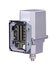
• Equipped terminal box standardly (LEDs can be visually checked from outside)
Typical Applications
• Actuator for automatic control valve in various plants and industries
• Electronic actuator for fuel cell system and refrigerating machines
MODEL: MRP10–[1][2][3]–[4]CR[5]
ORDERING INFORMATION
• Code number: MRP10-[1][2][3]-[4]CR[5]
Specify a code from below for each of [1] through [5].
(e.g. MRP10-1AA-ACR/Q)
• Specify the specification for option code /Q
(e.g. /C03/SET)
[1] OUTPUT STEM OPERATIONAL ANGLE
1: 90 degrees
[2] OPERATION TORQUE, OPERATION TIME
(90 DEGREES), TORQUE AT LOCK (MAX. VALUE)
[3] INPUT
Current
A: 4 – 20 mA DC (Input resistance 250 Ω)
Voltage
6: 1 – 5 V DC (Input resistance 200 kΩ min.)
[4] OUTPUT
Current
A: 4 – 20 mA DC (Load resistance 300 Ω max.)
Voltage
6: 1 – 5 V DC (Load resistance 5 kΩ min.)
CE & UKCA MARKING
C: With CE and UKCA
POWER SUPPLY VOLTAGE
DC Power
R: 24 V DC
(Operational voltage range 24 V ±10 %, ripple 10 %p-p max.)
[5] OPTIONS
blank: none
/Q: With options (specify the specification)
SPECIFICATIONS OF OPTION: Q (multiple selections)
COATING (For the detail, refer to our web site.)
/C03: Rubber coating
EX-FACTORY SETTING
/SET: Preset according to the Ordering Information Sheet
(No. ESU-4889)
RELATED PRODUCTS
• PC configurator software (model: STCFG)
• Programming Unit (model: PU-2x)
GENERAL SPECIFICATIONS
Degree of protection: IP66
Action: "Reverse" action (switchable with DIP switch to "direct" action.)
Operation at low input:
· Stop at full-open position
· Stop at full-close position
· hold position (ex-factory setting)
Low input signal level
· Current input: ≤ 1.48 (±0.2) mA DC
· Voltage input: ≤ 0.37 (±0.05) V DC
Wiring conduits: G 1/2 female thread and G 3/4 female thread (total four)
Terminal block: 7.62 mm pitch; M3 screw terminals (torque 0.5 N·m)
Screw terminal: Nickel-plated brass (not magnet)
Housing material: Diecast aluminum (ADC12)
Coating: Thermosetting acrylic resin
Coating: Silver color
Drive: Stepping motor
Insulation class: E
Position detection: Conductive potentiometer
Deadband adjustment: 0.1 – 0.5 % (1/1000 to 1/200)
Restart limiting timer adjustment: 0.1 – 5.0 sec.
Isolation: Power voltage or I/O signal to full-open signal position to full-close signal position to alarm signal to Modbus communication to metallic housing
Protective functions
· Automatically stops when torque at lock
· Automatically stops when surface temperature of the stepping motor is over 100°C (212°F) and automatically restarts under 95°C (203°F).
· Automatically heats to +2°C (35.6°F) when surface temperature of the stepping motor is under 0°C (32°F). The motor continues to run.
· A heater is incorporated to use under cold areas.
· Thermostat is incorporated to automatically heat when 27°C (±5°C) (80.6°F (±9°F) or lower, and automatically stop heating when 39°C (±4°C) (102.2°F (±7.2°F)) or higher.
Status Indicator LED
· POWER: Green LED turns on when the power voltage is ON
· INPUT: Green LED turns on with normal input signal
· MOVING UP/CCW.: Green LED turns on when full-open
· MOVING DOWN/CW.: Green LED turns on when full-close
· COM: Green LED turns ON while Modbus communication
· ALARM: Red LED blinks when abnormal operation
(For details, refer to users manual)
User-configurable items:
Configurable with DIP switch
· Stem operation at low input
· Switching direct/reverse
· Switching signal output
· Set full-open position
· Set full-close position
Configurable with PC or PU-2x
· Set full-open position
· Set full-closed position
· Deadband
· Restart limiting timer
· Full-open signal position
· Full-close signal position
· Output stem operation angle
Configurable with Modbus communication
· Input
· Node address
· Baud rate
· Parity bit
· Stop bit length
· Internal terminating resistor
· Loss of Modbus communication detection time
Action: Switching range of reverse/direct (following table)
· Increasing input signal, output stem moves to the full-open side (reverse)
· Increasing input signal, output stem moves to the dull-close side (direct)
MODBUS COMMUNICATION
Communication: Half-duplex, asynchronous, no procedure
Standard: TIA/EIA-485-A compatible
Transmission distance: 500 meters max.
Baud rate: 4800, 9600, 19200, 38400 bps
(ex-factory setting: 38400 bps)
Protocol: Modbus RTU
Node address: 1 to 247 (ex-factory setting: 1)
Parity: None, Odd, Even
Stop bit: 1, 2
Max. number of nodes: 31 (excluding master)
Transmission media: Shielded twisted-pair cable (CPEV-S 0.9 dia.)
Internal terminating resistor: 120 Ω
OUTPUT SPECIFICATIONS
■ Output signal
• 4-20 mA DC or 20-4 mA DC (non-isolated)
Load resistance: 300 Ω max.
• 1-5 V DC or 5-1 V DC (non-isolated)
Load resistance: 5 kΩ min.
■Full-open signal, full-close signal (CCW SIG., CW SIG.)
• Output type: Photo MOSFET relay
• Rated load: 160 V 150 mA AC/DC at peak
• ON resistance: 8 Ω max.
• Leakage current during opening/closing: 2 μA max.
■ Alarm output (triggered when the output stem is locked)
• Output type: Photo MOSFET relay
• Rated load: 160 V 150 mA AC/DC at peak
• ON resistance: 8 Ω max.
• Leakage current during opening/closing: 2 μA max.
STROKE RATE
Duty cycle = Within 50 %
The unit must operate at an average duty cycle of 50% (ratio of operating time to standby time) or less.
Operation rate: Less than 13 strokes / min. (excepting momentary peak stroke rate)
INSTALLATION (POWER VOLTAGE: @ 24 V DC)
Operating temperature: -25 to +66°C (-13 to 150.8°F) (No direct sunlight, radiant heat or heat transfer.)
Storage temperature: -29 to +70°C (-20.2 to 158°F)
Operating humidity: 30 to 90 %RH (non-condensing)
Vibration resistance:
• Sweep endurance test (IEC 61298-3 compliant)
• Acceleration: 19.6 m/s2 (2 G)
• Frequency: 10 to 1000 Hz
• Cycle: 20 cycles
• Sweep rate: 1 oct./min.
• Testing time: approx. 4 hr. 30 min.
• Direction: X, Y, Z
Mounting orientation:
DO NOT mount upside-down
Weight: Approx. 4.4 kg (8.820 lb)
PERFORMANCE
Resolution: 0.1%
Hysteresis: 0.6%
Linear characteristic: 1%
Backlash: 0.3 degrees
Insulation resistance: ≥ 100 MΩ with 500 V DC
(Power voltage or I/O signal to full-open signal to full-close signal to alarm signal to Modbus communication to metallic housing)
Dielectric strength: 500 V AC @ 1 minute (or 600 V AC @ 1 second)
(Power voltage or I/O signal to full-open signal to full-close signal to alarm signal to communication to metallic housing)
STANDARDS & APPROVALS
■ EU conformity (CE marking)
•EMC Directive
EMI EN 61000-6-4
EMS EN 61000-6-2
RoHS Directive
EN IEC 63000
--------------------
CÔNG TY CỔ PHẦN KỸ THUẬT VÀ THƯƠNG MẠI THIẾT BỊ CÔNG NGHIỆP NTD
Adress: No. 28, Alley 36 Co Linh Street, Group 7, Long Bien Ward, Long Bien District, Hanoi City, Vietnam.
Hotline: 0971961212
Mail: sales@ntd-automation.com
Hỗ trợ trực tuyến

Mobile:
Tel:


