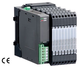
R6N-DC4A NPN TRANSISTOR OUTPUT MODULE, 4 points
Remote I/O R6 Series
NPN TRANSISTOR OUTPUT MODULE, 4 points
(NPN, Screw terminal)
Functions & Features
• 4-channel discrete output, compact size remote I/O module
MODEL: R6N–DC4A[1]
ORDERING INFORMATION
• Code number: R6N-DC4A[1]
Specify a code from below for [1].
(e.g. R6N-DC4A/Q)
• Specify the specification for option code /Q
(e.g. /C01)
[1] OPTIONS
blank: none
/Q: With options (specify the specification)
SPECIFICATIONS OF OPTION: Q
COATING (For the detail, refer to our web site.)
/C01: Silicone coating
/C02: Polyurethane coating
RELATED PRODUCTS
• PC configurator software (model: R6CON)
Downloadable at our web site.
A dedicated cable is required to connect the module to the PC. Please refer to the internet software download site or the users manual for the PC configurator for applicable cable types.
GENERAL SPECIFICATIONS
Connection
Internal bus: Via the Installation Base (model: R6N-BS)
Output: M3 screw terminals (torque 0.5 N·m)
Internal power: Via the Installation Base (model: R6N-BS)
Recommended solderless terminal: Max. 5.8 mm (0.23”)
wide; Ones with insulation sleeve do not fit.
Applicable wire size: 0.2 – 2.5 mm2
Housing material: Flame-resistant resin (black)
Isolation: Output to internal bus or internal power
Module address: Selectable with DIP and rotary switches on the side
Output at the loss of communication: Selectable with the side DIP SW
Configuration mode: With DIP switches on the side panel
Power indicator: Green LED; Refer to the istruction manual for details.
Status indicator: Bi-color (red/green) LED;
Refer to the instruction manual for details.
Discrete output status indicators: Red LED;
Refer to the instruction manual for details.
■Recommended solderless terminal (unit: mm [inch])
OUTPUT
Common: Negative common (NPN) per 4 points
Number of I/O: Output, 4 points
Maximum outputs applicable at once: No limit (at 24 V DC)
Rated load voltage: 24 V DC ±10 %
Rated output current: 0.25 A per point, 2.0 A per common
Residual voltage: ≤ 1.2 V
Leakage current: ≤ 0.1 mA
ON delay: ≤ 0.5 msec.
OFF delay: ≤ 1.5 msec.
(When driving an inductive load, connect a diode in parallel with the load.)
INSTALLATION
Current consumption: 20 mA
Operating temperature: -10 to +55°C (14 to 131°F)
Operating humidity: 30 to 90 %RH (non-condensing)
Atmosphere: No corrosive gas or heavy dust
Mounting: Installation Base (model: R6N-BS)
Weight: 60 g (2.1 oz)
PERFORMANCE
Data allocation: 1
Insulation resistance: ≥ 100 MΩ with 500 V DC
Dielectric strength: 1500 V AC @ 1 minute
(output to internal bus or internal power to ground)
STANDARDS & APPROVALS
EU conformity:
EMC Directive
EMI EN 61000-6-4
EMS EN 61000-6-2
RoHS Directive
EXTERNAL VIEW
Refer to the instruction manual for setting procedures.


